
The Quantum Divide: Band Theory and Electron Flow
When building a custom battery pack, wiring a 240V subpanel, or designing a high-frequency RF circuit, understanding the fundamental insulator and conductor difference is not just academic—it is the boundary between a functional system and a catastrophic fire. While basic physics teaches us that conductors allow electron flow and insulators block it, professional electrical engineering requires a deeper grasp of quantum mechanics, specifically band theory.
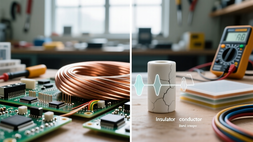
In solid-state physics, electrons exist in energy bands. The valence band contains the outermost electrons bound to an atom, while the conduction band is where electrons are free to move and carry current. The insulator and conductor difference fundamentally comes down to the bandgap—the energy barrier between these two bands. According to Georgia State University's HyperPhysics, conductors (like copper and silver) have overlapping valence and conduction bands, meaning electrons require virtually zero additional energy to flow. Insulators, conversely, possess a massive bandgap (typically greater than 3 electron volts), locking electrons tightly to their parent atoms and preventing current flow under normal conditions.
Material Showdown: Conductors in Real-World Wiring
In practical DIY and industrial applications, we do not just look for any conductor; we look for the optimal balance of conductivity, tensile strength, weight, and cost. The standard metric used is the International Annealed Copper Standard (IACS), where pure annealed copper is set at 100% conductivity.
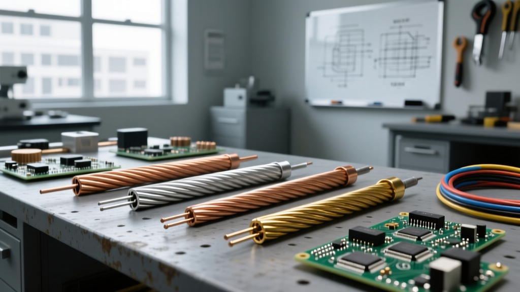
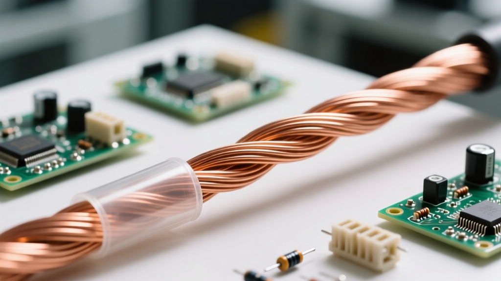
- Copper (Cu): The undisputed king of residential and commercial wiring. With a resistivity of roughly 1.68 × 10⁻⁸ Ω·m at 20°C, it offers exceptional conductivity and high ductility. It easily pulls through conduit and resists creep under screw terminals.
- Aluminum (Al): Operating at about 61% IACS, aluminum is lighter and significantly cheaper. It is the standard for utility drop lines and large feeder wires (e.g., 4/0 AWG for 200A residential services). However, it requires antioxidant paste and specific torque settings to prevent cold-flow creep and subsequent arcing.
- Silver (Ag): While technically the most conductive element (roughly 105% IACS), silver is rarely used in bulk wiring due to cost. It is primarily found in high-end audio contacts, aerospace relays, and specialized RF components where skin effect resistance must be minimized.
For precise resistivity data across various temperatures, The Engineering Toolbox provides comprehensive metallurgical tables that are essential for calculating voltage drop over long wire runs.
The Insulator Arsenal: Dielectric Strength and Limits
An insulator's primary job is to contain the electric field within the conductor and protect users from shock. However, no insulator is perfect. The critical metric here is dielectric strength, measured in kilovolts per millimeter (kV/mm) or megavolts per meter (MV/m). This defines the exact voltage gradient at which the insulator's bandgap is overcome, causing a violent, destructive flow of current known as dielectric breakdown.
- Polyvinyl Chloride (PVC): The most common jacket for THHN/THWN building wire. It offers a dielectric strength of roughly 40 kV/mm and is rated for 90°C in dry locations. It is cheap and flexible but degrades under high UV exposure and extreme heat.
- Cross-Linked Polyethylene (XLPE): By chemically cross-linking the polymer chains, XLPE achieves superior thermal stability and a dielectric strength of roughly 25 to 30 kV/mm (depending on density). It is the standard for medium and high-voltage underground distribution cables.
- Polytetrafluoroethylene (PTFE / Teflon): Used in aerospace, military, and high-temperature electronics. PTFE boasts an incredible dielectric strength (up to 60 kV/mm) and can withstand continuous operating temperatures up to 260°C without melting or off-gassing toxic fumes.
Head-to-Head Comparison: The Insulator and Conductor Difference
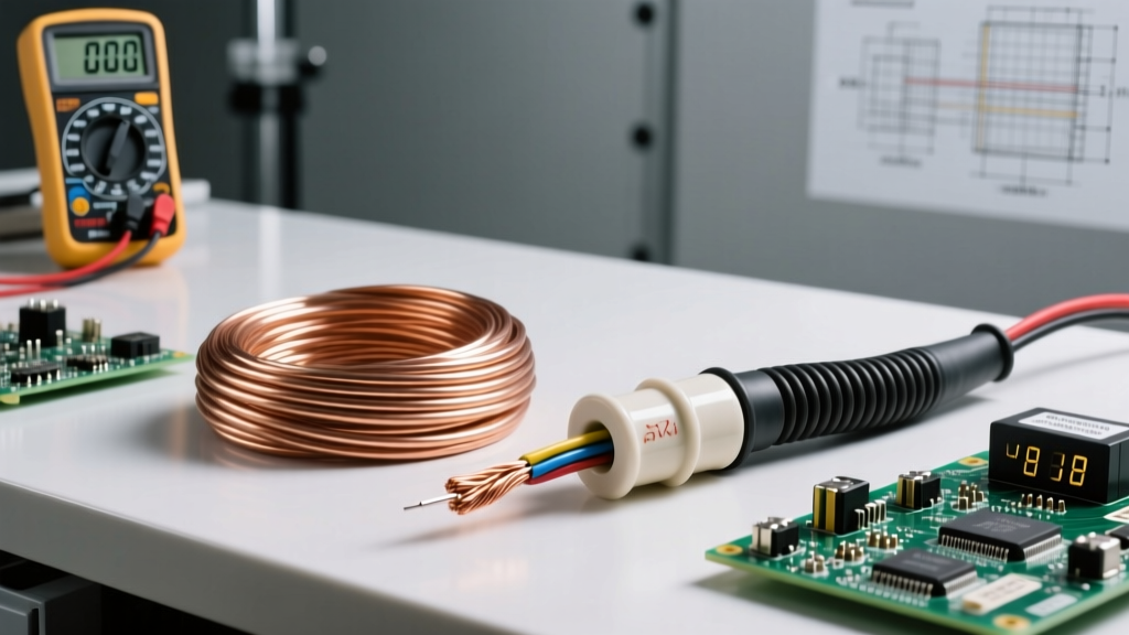
To visualize the stark contrast between these two classes of materials, consider the following comparison between standard electrical grade copper and XLPE insulation.
| Property | Conductor (Copper) | Insulator (XLPE) |
|---|---|---|
| Primary Function | Facilitate electron flow | Contain electric field / Block current |
| Bandgap Energy | 0 eV (Overlapping bands) | > 8 eV (Wide gap) |
| Resistivity (20°C) | ~1.68 × 10⁻⁸ Ω·m | > 10¹⁴ Ω·m |
| Thermal Coefficient | Positive (Resistance rises with heat) | Negative (Resistance drops with heat) |
| Failure Mechanism | Melting, Oxidation, Electromigration | Dielectric Breakdown, Tracking, UV degradation |
Thermal Coefficients: How Heat Rewrites the Rules
One of the most critical, yet frequently overlooked, aspects of the insulator and conductor difference is how they react to temperature changes. This is defined by their thermal coefficients of resistance.
Conductors exhibit a Positive Temperature Coefficient (PTC). As a copper wire heats up due to I²R (current squared times resistance) losses, the atomic lattice vibrates more violently. This increased vibration scatters the flowing electrons, raising the wire's resistance. This is why voltage drop calculations must account for ambient temperature and conduit fill derating, as outlined in the NFPA 70 National Electrical Code (NEC).
Insulators exhibit a Negative Temperature Coefficient (NTC). As an insulator heats up, the thermal energy actually helps excite some electrons across the massive bandgap. This means that as an insulated wire gets hotter, the insulation's resistance decreases, making it slightly more prone to leakage current. This is a vital concept when designing high-temperature motor windings or routing wires near exhaust manifolds in automotive applications.
Failure Modes: When Conductors Insulate and Insulators Conduct
In the real world, materials rarely fail in the way textbooks suggest. Understanding failure modes is crucial for troubleshooting complex electrical faults.
When Insulators Conduct: Dielectric Breakdown and Tracking
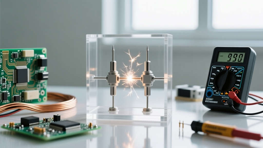
If you exceed the dielectric strength of an insulator, it undergoes avalanche breakdown. The immense electric field literally tears electrons from their atoms, creating a conductive plasma channel. In solid insulators like PVC, this leaves behind a carbonized track. Because carbon is a conductor, this "tracking" creates a permanent, low-resistance short circuit, often resulting in a sustained arc fault that standard breakers might not immediately trip.
When Conductors Insulate: Oxidation and the Skin Effect
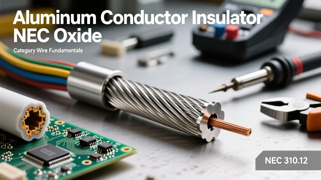
Ironically, the most common cause of electrical fires is a conductor acting as an insulator. When aluminum or copper is exposed to oxygen and moisture, it forms an oxide layer. Aluminum oxide (Al₂O₃) is actually a highly effective electrical insulator. If a wire terminal is not properly torqued or treated with antioxidant compound, this insulating oxide layer creates a high-resistance joint. The joint heats up, accelerating the oxidation in a runaway thermal cycle until the connection melts or ignites surrounding materials.
Pro-Tip for High-Frequency DIY: In RF and high-frequency AC applications, the "skin effect" forces current to flow only on the outermost microscopic layer of the conductor. If your copper wire is heavily oxidized or tarnished, the current is forced to travel through the insulating oxide layer, causing massive signal attenuation. Always clean high-frequency conductors with isopropyl alcohol and a fiberglass scratch brush before soldering.
Practical Troubleshooting: Megohmmeter Testing for Insulation Breakdown
Because the insulator and conductor difference degrades over time due to heat, moisture, and mechanical stress, professional electricians do not rely solely on standard multimeters to check wire health. A standard multimeter uses a few volts to test continuity, which is entirely insufficient for evaluating insulation integrity.
Instead, we use a Megohmmeter (or "Megger"). This device injects high-voltage DC (typically 250V, 500V, or 1000V) into the wire to stress the insulation without causing a breakdown. By measuring the micro-amps of leakage current that manage to cross the insulator's bandgap, the tool calculates the insulation resistance in Megohms (MΩ).
- > 100 MΩ: Excellent insulation health. The bandgap is fully intact.
- 10 MΩ to 100 MΩ: Acceptable for older wiring, but indicates the beginning of dielectric degradation or moisture ingress.
- < 2 MΩ: Critical failure imminent. The insulator is actively conducting leakage current and must be replaced immediately to prevent ground faults or shock hazards.
Ultimately, mastering the insulator and conductor difference means looking beyond the binary of "flows" and "blocks." It requires understanding the quantum boundaries of materials, respecting their thermal limits, and utilizing the right diagnostic tools to ensure your electrical systems remain safe, efficient, and code-compliant for decades.