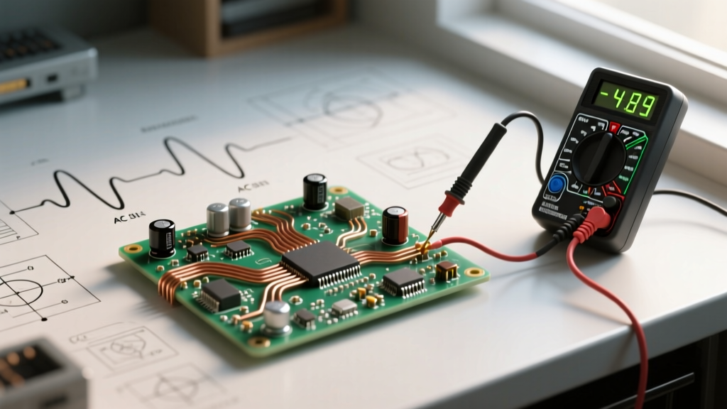

When you plug a power tool into a wall outlet or wire a new 240V circuit for a workshop compressor, you are interacting with the most ubiquitous energy delivery system on the planet. But for DIYers and electrical enthusiasts, understanding the fundamental physics behind the power grid is critical for safety and proper wire sizing. If you have ever asked yourself, what does AC electricity mean in a practical, real-world sense, you are not alone. The answer lies not just in textbook definitions, but in how alternating current behaves differently from direct current (DC) when pushed through copper conductors.
In this comprehensive comparison guide, we will break down the exact meaning of Alternating Current (AC), contrast it with Direct Current (DC), and explore the physical phenomena—like the skin effect and RMS voltage—that dictate how we size wires, select breakers, and troubleshoot circuits in 2026 and beyond.
The Core Definition: What Does AC Electricity Mean in Practice?
At its most basic level, Alternating Current (AC) is an electrical current in which the flow of electric charge periodically reverses direction. Unlike a battery-powered DC circuit, where electrons march steadily from the negative terminal to the positive terminal, electrons in an AC circuit essentially vibrate back and forth in place.
In North America, this reversal happens 60 times per second, a frequency measured as 60 Hertz (Hz). In Europe and many other parts of the world, the standard is 50 Hz. According to the U.S. Energy Information Administration, this oscillating nature is what allows AC to be easily transformed to different voltages, making it the undisputed king of long-distance power transmission.
The Mechanical Analogy
Imagine a handsaw cutting through a piece of wood. DC is like a chainsaw's continuous loop cutting in one direction. AC is like a traditional crosscut handsaw: the blade moves forward, then backward, over and over. Even though the blade changes direction, the work (cutting the wood, or in electrical terms, generating heat and doing work) still gets done. This is why AC can power a resistive load like an incandescent bulb or a space heater just as effectively as DC.
Waveform Anatomy: Sine Waves vs. Flat Lines
To truly grasp the difference between AC and DC, we must look at their waveforms on an oscilloscope. DC presents as a flat, horizontal line. If you have a 12V car battery, the voltage sits at a steady 12V (or roughly 12.6V when fully charged and resting).
AC, however, presents as a sine wave. The voltage starts at zero, rises to a positive peak, drops back through zero to a negative peak, and returns to zero. This creates a massive point of confusion for beginners regarding voltage ratings.
The RMS vs. Peak Voltage Trap
When we say a standard North American outlet is "120V AC," we are not talking about the peak voltage. We are referring to the Root Mean Square (RMS) voltage. RMS is a mathematical method of expressing an AC voltage in terms of the equivalent DC voltage that would produce the same amount of heat in a resistive load.
- RMS Voltage: 120V (The "working" voltage used for wire sizing and Ohm's Law calculations).
- Peak Voltage: ~170V (Calculated as $V_{rms} \times \sqrt{2}$, or $120 \times 1.414$).
- Peak-to-Peak Voltage: ~340V (The total swing from the positive peak to the negative peak).
This distinction is vital for DIYers selecting components. If you are buying a capacitor or a solid-state relay for a 120V AC circuit, the component must be rated to withstand the 170V peak, not just the 120V RMS, or it will suffer dielectric breakdown and fail catastrophically. For a deeper dive into the math, Georgia State University's HyperPhysics provides excellent foundational formulas on AC/DC waveforms.
Head-to-Head Comparison: AC vs. DC Power Characteristics
How do these two current types stack up against each other across critical electrical vectors? The table below outlines the primary differences that affect everything from grid infrastructure to your home workshop.
| Characteristic | Alternating Current (AC) | Direct Current (DC) |
|---|---|---|
| Electron Flow | Oscillates back and forth (bidirectional) | Flows continuously in one direction (unidirectional) |
| Waveform | Sine wave (typically) | Flat, steady line |
| Frequency | 50 Hz or 60 Hz (grid standard) | 0 Hz (Zero frequency) |
| Long-Distance Transmission | Highly efficient via step-up transformers | Historically poor, but modern HVDC is highly efficient for ultra-long distances |
| Energy Storage | Cannot be stored directly; requires conversion | Can be stored natively in batteries and capacitors |
| Wire Sizing Factor | Subject to "Skin Effect" at high currents/frequencies | Current distributes evenly across the entire wire cross-section |
| Typical Sources | Alternators, utility grid, inverters | Batteries, solar panels, rectifiers |
Why the Grid Chose AC: The Transformer Advantage
The historical "War of the Currents" between Thomas Edison (championing DC) and Nikola Tesla/George Westinghouse (championing AC) was ultimately decided by a single physical principle: $I^2R$ power loss.
When electricity travels through a wire, it loses energy as heat. This loss is proportional to the square of the current ($I^2$) multiplied by the resistance of the wire ($R$). To deliver massive amounts of power ($P = V \times I$) over hundreds of miles, you can either send high current at low voltage, or low current at high voltage.
Because AC voltage can be easily stepped up to 500,000 volts using simple transformers, the current drops dramatically, minimizing $I^2R$ heat losses on the transmission lines. Once the power reaches your neighborhood, a pole-mounted transformer steps it back down to a safe 240V/120V split-phase system for residential use. DC lacks this simple magnetic transformation capability, which is why AC won the grid war in the late 19th century.
Note on Modern HVDC: Today, High Voltage Direct Current (HVDC) is making a comeback for point-to-point lines exceeding 500 miles (like the 3,100 MW Pacific DC Intertie). Advances in solid-state power electronics now allow DC to be stepped up and down efficiently, bypassing the capacitive losses that plague ultra-long AC lines.
Practical DIY Implications: Wiring AC vs. DC Circuits
Understanding what AC electricity means translates directly into how you pull wire, terminate connections, and size breakers in the field. Here are the critical differences DIYers must respect.
1. The Skin Effect in AC Wire Sizing
Because AC current constantly reverses direction, it generates a changing magnetic field inside the conductor. This creates eddy currents that push the electron flow toward the outer surface, or "skin," of the wire. This is known as the skin effect.
At 60Hz, the skin depth in copper is approximately 8.5mm. For standard residential wiring like 14 AWG or 12 AWG THHN (which have diameters well under 2mm), the skin effect is negligible. The entire cross-section of the wire is utilized. However, if you are sizing massive 500 MCM or 1000 MCM feeders for a commercial AC panel, the center of the copper is essentially dead weight. This is why high-amperage AC busbars are often hollow or constructed from multiple stacked copper strips to maximize surface area.
2. Polarity and Conductor Identification
In a DC circuit, polarity is absolute. You have a Positive (+) and a Negative (-). Reversing them can destroy sensitive electronics or cause DC motors to run backward.
In a standard single-phase AC circuit, we use Hot (ungrounded), Neutral (grounded), and Ground (equipment grounding conductor). Because the current alternates, the "Hot" wire alternates between being positive and negative relative to the neutral 120 times a second. However, for safety, the NEC strictly requires the neutral to be bonded to earth ground at the main service panel, ensuring it remains at or near 0V potential relative to the earth.
Troubleshooting Common AC Misconceptions
The Myth: "My multimeter reads 120V, so the AC waveform is perfectly clean and safe for my sensitive CNC router electronics."
This is a dangerous assumption in modern electrical environments. Not all AC waveforms are perfect sine waves. When you use Variable Frequency Drives (VFDs), cheap solar inverters, or LED dimmer switches, they often chop the AC sine wave into square or modified waves using Pulse Width Modulation (PWM).
If you use a standard, budget-friendly "average-responding" multimeter to measure a chopped AC waveform, the meter will assume a perfect sine wave and apply an internal scaling factor. The result? Your meter might display 120V, while the actual RMS voltage is spiking at 150V, slowly degrading the insulation on your motor windings or frying the power supply of your CNC controller.
To troubleshoot modern AC circuits accurately, you must invest in a True RMS multimeter. As detailed by Fluke Corporation's electrical testing guidelines, True RMS meters sample the waveform thousands of times per second, calculating the actual heating value of the distorted wave regardless of its shape. If you are doing any advanced DIY work involving inverters, VFDs, or smart home dimmers, a True RMS meter is non-negotiable.
Summary: Mastering the Alternating Current
So, what does AC electricity mean for the modern DIYer? It means working with a dynamic, oscillating force that requires a deep respect for peak voltages, frequency-dependent phenomena like the skin effect, and strict adherence to grounding and bonding rules. While DC remains the king of portable electronics, battery storage, and solar arrays, AC is the lifeblood of the heavy-duty grid and high-power workshop tools. By understanding the fundamental differences outlined in this comparison guide, you can confidently size conductors, select the right testing equipment, and build electrical systems that are both efficient and safe.