
The Core Definition: What Is Direct Current Electricity?
At its most fundamental level, what is direct current electricity? Direct current (DC) is a type of electrical current where the flow of electric charge occurs in only one direction. Unlike alternating current (AC), which periodically reverses its direction and voltage polarity, DC maintains a constant, unidirectional flow of electrons from the negative terminal (anode) to the positive terminal (cathode) of the power source. This steady, unvarying potential difference makes DC the undisputed standard for energy storage, electrochemistry, and modern digital electronics.
For DIYers, marine electricians, and solar installers, understanding DC is not just about theory; it is about managing high-amperage, low-voltage environments where wire sizing and connection integrity are critical to preventing fires and equipment failure.
Electron Flow & Circuit Dynamics in DC Systems
In a DC circuit, the voltage remains nominally constant over time, creating a flat line on an oscilloscope (ignoring minor ripple from rectifiers). Because the current does not alternate, DC systems do not experience the skin effect—a phenomenon in AC systems where high-frequency currents travel primarily on the outer surface of a conductor. In DC, the electron flow utilizes the entire cross-sectional area of the wire. While this is theoretically more efficient for conductor utilization, the low-voltage nature of most DC systems demands massive current to deliver usable power, fundamentally altering how we approach wire sizing.
Unidirectional Flow vs. Alternating Cycles
According to the U.S. Energy Information Administration (EIA), the primary distinction between AC and DC lies in the generation and transmission phases. AC is easily stepped up to high voltages for long-distance transmission, whereas DC is inherently tied to chemical generation (batteries, fuel cells) and photovoltaic generation (solar panels). To bridge the two, inverters and rectifiers are used, but the core DC circuit remains strictly unidirectional.
Standard DC Voltage Tiers: Application Matrix
When designing or troubleshooting a DC system, identifying the voltage tier is the first step in determining wire gauge, insulation requirements, and overcurrent protection. Below is a reference chart of standard DC voltages encountered in residential, commercial, and off-grid applications.
| DC Voltage Tier | Primary Applications | Typical Power Range | Wire Sizing Considerations |
|---|---|---|---|
| 5V / 12V | USB charging, automotive accessories, RV lighting, small marine electronics. | 10W - 1,200W | Extremely high current. Requires oversized conductors (e.g., 1/0 AWG for 100A+ inverter loads) to mitigate voltage drop. |
| 24V | Off-grid solar banks, heavy-duty marine systems, trucking fleets, electric mobility. | 500W - 3,000W | Moderate current. 6 AWG to 2 AWG typically sufficient for main battery-to-inverter trunks. |
| 48V | Telecom towers, data centers, residential solar storage (e.g., Tesla Powerwall, server rack batteries). | 2,000W - 10,000W+ | Optimal balance of safety and efficiency. Main trunks often use 2/0 or 4/0 AWG depending on continuous load. |
| 380V (HVDC) | Data center busways, high-voltage direct current transmission, EV fast-charging architectures. | 50kW - Megawatts | Requires specialized insulation, strict clearance distances, and arc-flash mitigation. |
The DC Penalty: Voltage Drop and Wire Sizing Realities
The most critical concept for any electrical flux practitioner to grasp is the "DC Penalty." Because power (Watts) equals Voltage multiplied by Current ($P = V \times I$), dropping the voltage drastically increases the current required to deliver the same amount of power. High current leads to severe $I^2R$ (heat) losses and crippling voltage drop over distance.
Calculating the Impact: 12V vs. 48V Inverter Sizing
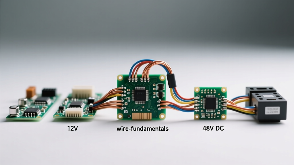
Consider a 2,400W inverter load. Let us calculate the current draw and required copper for both a 12V and a 48V system, assuming a 3% maximum allowable voltage drop over a 10-foot one-way cable run:
- 12V System: 2,400W / 12V = 200 Amps (accounting for inverter inefficiency, peak draw can exceed 220A). To maintain a 3% voltage drop (0.36V max drop) over 10 feet, you must use 4/0 AWG pure copper welding cable.
- 48V System: 2,400W / 48V = 50 Amps. To maintain a 3% voltage drop (1.44V max drop) over 10 feet, 6 AWG copper wire is perfectly adequate.
This stark comparison illustrates why modern solar and off-grid systems have largely migrated to 48V DC architectures. The material cost and physical stiffness of 4/0 AWG cable make 12V systems highly impractical for anything beyond small RVs or boats.
NEC Compliance Note: When sizing DC conductors, always refer to NFPA 70: National Electrical Code (NEC) Article 690 for Solar Photovoltaic Systems. The NEC requires conductors to be sized at 125% of the maximum continuous current, and voltage drop should be strictly managed to prevent inverter low-voltage disconnects.
AC vs. DC: Component & Safety Comparison
Direct current electricity behaves fundamentally differently than AC when a circuit is broken. In an AC circuit, the voltage crosses zero 120 times per second (in a 60Hz system). When a breaker trips or a switch opens, this zero-crossing naturally extinguishes the electrical arc. DC has no zero-crossing. When a DC circuit is interrupted, the arc sustains itself, drawing out into a continuous, extremely hot plasma that can melt breaker contacts and start fires.
| Component | AC System Behavior | DC System Behavior & Requirements |
|---|---|---|
| Circuit Breakers | Standard thermal-magnetic breakers rely on AC zero-crossing to quench arcs. | Must use specialized DC-rated breakers (e.g., Midnite Solar MNEPV, Schneider C60DC) with internal magnetic blowouts or arc chutes to force the arc into extinction. |
| Switches & Relays | Standard toggles and contactors handle standard residential loads safely. | DC switches require higher voltage/current ratings and wider contact gaps. Using an AC toggle switch on a 48V DC battery bank will result in the switch welding itself shut or catching fire. |
| Fuses | Standard glass or ceramic fuses. | Requires High-Interrupting Capacity (HRC) fuses like Class T or ANL fuses. A standard automotive AGU fuse can explode when subjected to a dead short on a large lithium battery bank due to the massive fault current DC batteries can deliver. |
Troubleshooting Common DC Circuit Failures
Because DC systems operate at lower voltages, they are highly susceptible to connection degradation and environmental factors that AC systems might simply push through. Here are three specific failure modes unique to DC environments:
1. Galvanic Corrosion and Stray DC Currents
In marine and automotive environments, stray DC current leaking into a bilge or chassis can cause rapid galvanic corrosion. If a 12V positive wire chafes against a metal hull, the DC current will use the surrounding water or metal as a return path to the battery negative. This electrolytic reaction eats away at propellers, through-hulls, and aluminum frames in a matter of weeks. Fix: Always use marine-grade tinned copper wire (like Ancor) and ensure all DC negative buses are properly bonded to a common ground point to prevent stray voltage gradients.
2. Thermal Runaway at High-Resistance Connections
Because DC systems rely on high amperage, even a slightly loose lug on a battery terminal creates a high-resistance point. According to Joule's First Law ($P = I^2R$), a connection with just 0.05 ohms of resistance carrying 100A will dissipate 500 Watts of pure heat at that single joint. This quickly melts insulation and causes terminal fires. Fix: Use a calibrated torque wrench on all DC busbars and battery lugs, and apply dielectric grease to prevent oxidation, which increases resistance over time.
3. Voltage Drop Induced Inverter Faults
A common troubleshooting scenario in off-grid solar involves an inverter shutting down under heavy load, displaying a "Low Battery Voltage" error, even though the battery monitor reads 13.2V. This is caused by undersized DC wiring. Under a 150A load, the voltage drop across thin or overly long cables can pull the voltage at the inverter's terminals down to 10.5V, triggering the low-voltage cutoff. Fix: Measure voltage directly at the inverter terminals while under load, not at the battery, to diagnose hidden DC voltage drop.
Understanding what direct current electricity is goes far beyond a basic physics definition. It requires a practical, safety-first approach to wire sizing, arc mitigation, and connection integrity. By respecting the high-current realities of DC, you can build resilient, efficient systems for solar, marine, and automotive applications.