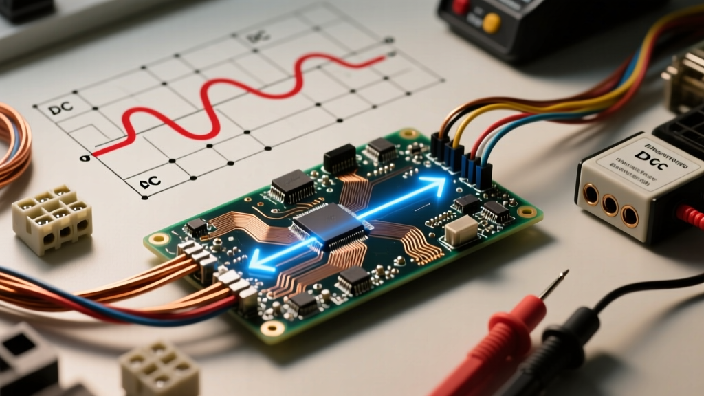

Decoding the DC Meaning in Electricity
When makers, solar installers, marine technicians, and automotive engineers search for the dc meaning electricity, they are usually looking for more than just a textbook definition. Direct Current (DC) is the backbone of modern electronics, renewable energy systems, and electric vehicles. Unlike Alternating Current (AC), which periodically reverses direction, DC flows unidirectionally. However, understanding the true dc meaning in electricity requires diving into electron physics, wiring mechanics, and the unique safety challenges that DC presents in real-world applications.
In this comprehensive reference guide, we will break down the physics of DC, compare it directly to AC, and provide actionable wire sizing charts and voltage drop tables critical for any DIY electrical project or professional installation.
The Physics: Electron Flow vs. Conventional Current
To truly grasp DC fundamentals, we must address a historical quirk in electrical engineering. When you wire a DC circuit—such as connecting a 12V lithium iron phosphate (LiFePO4) battery to a Victron inverter—you are dealing with two different models of current flow:
- Conventional Current: Pioneered by Benjamin Franklin, this model assumes current flows from the positive (+) terminal to the negative (-) terminal. Almost all modern schematics, multimeters, and diode symbols use this convention.
- Electron Flow: Discovered later with the identification of the electron, this physical reality dictates that negatively charged electrons actually repel from the negative terminal and flow toward the positive terminal.
Expert Insight: While electron flow is the physical reality, always design your DC wiring diagrams and trace your circuits using conventional current (positive to negative). This ensures compatibility with standard component symbols, fuse placements, and NEC compliance.
DC vs. AC: Technical Comparison Chart
Understanding the dc meaning electricity is best achieved by contrasting it with the AC power delivered by the utility grid. Below is a technical reference chart highlighting the operational differences that impact wiring and component selection.
| Parameter | Direct Current (DC) | Alternating Current (AC) |
|---|---|---|
| Flow Direction | Unidirectional (Constant) | Bidirectional (Sinusoidal) |
| Frequency | 0 Hz | 50 Hz or 60 Hz (Utility) |
| Power Factor | Always 1.0 (Unity) | 0 to 1.0 (Reactive loads) |
| Skin Effect | None (Uses full conductor) | Present (Current crowds to edges) |
| Zero Crossing | None (Continuous voltage) | 120 times/sec (at 60Hz) |
| Transmission | Highly efficient over HVDC lines | Standard for grid distribution |
Why the "Skin Effect" Matters for Wire Sizing
One of the most critical takeaways from the chart above is the Skin Effect. In AC circuits, especially at higher frequencies or massive amperages, electrons tend to travel along the outer "skin" of the conductor. This effectively reduces the usable cross-sectional area of the wire, increasing AC resistance.
In DC circuits, the frequency is 0 Hz. Therefore, DC utilizes the entire cross-sectional area of the wire. This means that for the exact same American Wire Gauge (AWG), a DC wire can sometimes handle thermal loads slightly more predictably than AC, provided voltage drop is managed. For high-current DC applications like 48V solar battery banks, stranded copper wire (like THHN or PV wire) is preferred for flexibility, but the entire copper bundle carries the current uniformly.
DC Wiring Challenges: Voltage Drop & Sizing
The biggest hurdle in DC electrical design is voltage drop. Because DC systems often operate at much lower voltages (12V, 24V, 48V) compared to AC (120V, 240V), even a tiny resistance in the wire results in a massive percentage of power loss. According to the National Electrical Code (NEC), branch circuit voltage drop should ideally not exceed 3%.
To calculate DC voltage drop, use the standard Circular Mil formula:
VD = (2 x K x I x L) / CM
- VD = Voltage Drop
- K = Specific Resistance (12.9 for Copper, 21.2 for Aluminum)
- I = Current in Amps
- L = One-way length of the wire in feet
- CM = Circular Mils of the conductor (found in NEC Chapter 9, Table 8)
For a deep dive into DC circuit mathematics and Ohm's law applications, the All About Circuits DC Textbook remains an industry-standard reference for engineers and DIYers alike.
DC Voltage Drop Reference Chart (12V, 24V, & 48V Systems)
Below is a quick-reference sizing chart for copper wire in common low-voltage DC systems. This chart assumes a maximum 3% voltage drop for a one-way distance of 10 feet (20 feet total round-trip circuit). If your run is longer, you must step up the wire gauge.
| Wire Gauge (AWG) | Max Amps (12V System) | Max Amps (24V System) | Max Amps (48V System) |
|---|---|---|---|
| 14 AWG | 5.8 A | 11.7 A | 23.5 A |
| 12 AWG | 9.3 A | 18.6 A | 37.3 A |
| 10 AWG | 14.8 A | 29.6 A | 59.3 A |
| 8 AWG | 23.5 A | 47.1 A | 94.3 A |
| 6 AWG | 37.4 A | 74.9 A | 149.9 A |
| 4 AWG | 59.6 A | 119.3 A | 238.7 A |
| 2/0 AWG | 190.2 A | 380.5 A | 761.1 A |
Note: Always cross-reference these voltage-drop limits with the NEC Ampacity tables (Table 310.16) to ensure the wire's insulation can handle the thermal load. The lower of the two values (voltage drop limit vs. thermal ampacity limit) dictates your final wire size.
Real-World Troubleshooting: DC Arcing and Safety
The most dangerous misunderstanding of the dc meaning electricity occurs when DIYers treat DC breakers like AC breakers. In an AC circuit, the current crosses zero volts 120 times a second (in a 60Hz system). This "zero-crossing" naturally helps extinguish the electrical arc that forms when a breaker trips under load.
DC has no zero-crossing. If a standard AC breaker is used in a high-voltage DC solar array (e.g., 300V DC from series-wired panels), the arc will sustain, melt the breaker internals, and potentially cause a fire.
Best Practices for DC Overcurrent Protection
- Use DC-Rated Breakers: Always use breakers specifically rated for DC voltage and current. For example, the Midnight Solar MNEPV series is rated for up to 150VDC, and specific Schneider Electric Square D QO breakers are rated for 125VDC (unlike standard HOM breakers, which are strictly AC).
- Polarity Matters: Many DC breakers and diodes are directional. Wiring a DC breaker backward can result in the magnetic blowout coil failing to extinguish the arc during a fault condition.
- Proper Grounding: According to Solar-Electric installation guidelines and NEC Article 690, DC systems must be properly bonded to the AC grounding electrode system to prevent lethal voltage potentials on equipment chassis during a ground fault.
Summary: Mastering DC Fundamentals
Understanding the dc meaning electricity goes far beyond knowing that it flows in one direction. It requires a fundamental respect for voltage drop, thermal limits, and the unforgiving nature of DC arcs. By utilizing the Circular Mil formula, respecting the skin effect (or lack thereof), and strictly adhering to DC-rated safety components, you can design robust, efficient, and safe direct current systems for any application. Whether you are wiring a 12V camper van or a 800V EV charging station, the physics of DC remain the same—only the scale changes.


