
Beyond the Lookup: Why Static Charts Fail in the Field
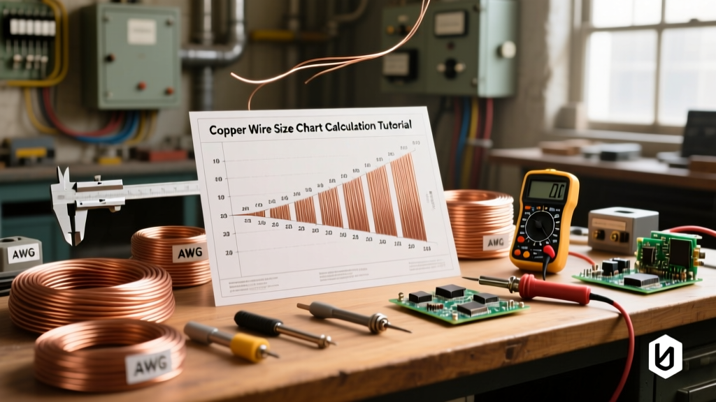
Most DIYers and junior electricians treat a copper wire size chart as a simple lookup table: find the amperage, match the American Wire Gauge (AWG), and pull the wire. While this works for short, basic residential runs, it is a dangerous oversimplification for workshops, marine applications, or long-distance feeds. A static chart cannot account for ambient temperature, conduit bundling, or the physics of voltage drop over distance.
In this calculation tutorial, we will deconstruct the standard copper wire size chart. You will learn how to calculate true ampacity based on termination temperatures, apply National Electrical Code (NEC) derating factors, and use circular mil formulas to guarantee your voltage drop stays within safe operational limits.
The Anatomy of a Copper Wire Size Chart
Before running calculations, you must understand the metrics defining the chart. The AWG system is logarithmic, not linear. The cross-sectional area of a wire doubles every time you drop three gauge sizes (e.g., from 12 AWG to 9 AWG) and increases tenfold every ten gauge sizes (e.g., from 10 AWG to 1/0 AWG).
Understanding Circular Mils (CM)
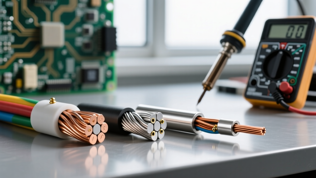
While AWG is the common nomenclature, electrical engineers and advanced sizing calculations rely on Circular Mils (CM). A circular mil is the area of a circle with a diameter of one mil (one-thousandth of an inch). When calculating voltage drop, the CM value is your most critical variable. For reference, 14 AWG is 4,110 CM, 12 AWG is 6,530 CM, and 10 AWG is 10,380 CM. You can find exact CM values on any comprehensive engineering wire gauge reference table.
Step 1: Calculating True Ampacity (The Termination Rule)
The most common mistake made when reading a copper wire size chart is referencing the 90°C ampacity column for THHN/THWN-2 wire. While the insulation can withstand 90°C, your terminations likely cannot.
NEC 110.14(C) mandates that the ampacity of a conductor must be selected based on the lowest temperature rating of any connected termination, conductor, or device. Most standard residential breakers and receptacles are rated for 60°C or 75°C.
Calculation Example: You are installing a 12 AWG copper wire (THHN). The 90°C column lists its ampacity at 30 Amps. However, because the standard receptacle is rated for 75°C (and 14-12-10 AWG are often restricted to the 60°C column per NEC Table 310.16 unless specific conditions are met), your maximum allowable ampacity is 20 Amps (60°C column) or 25 Amps (75°C column). You must size your overcurrent protection device (OCPD) based on this lower limit, not the wire's thermal maximum.
The Continuous Load Factor
If your circuit will operate at maximum current for three hours or more (e.g., a workshop dust collector, EV charger, or continuous lighting), NEC Article 210.20 requires you to multiply the continuous load by 125%. Therefore, a 16 Amp continuous load requires a conductor and breaker sized for 16A x 1.25 = 20A.
Step 2: Applying Bundling and Ambient Temperature Derating
A standard copper wire size chart assumes an ambient temperature of 30°C (86°F) and no more than three current-carrying conductors in a raceway. If your installation deviates from this, you must apply correction factors.
Bundling Derating (NEC Table 310.15(C)(1))
When current flows through copper, it generates heat. If you pull four to six current-carrying conductors through a single conduit, the trapped heat reduces the wire's ability to dissipate thermal energy. You must multiply the base ampacity (from the 90°C column for derating purposes) by 80%.
- 4-6 Conductors: Multiply base ampacity by 0.80
- 7-9 Conductors: Multiply base ampacity by 0.70
- 10-20 Conductors: Multiply base ampacity by 0.50
Note: Grounding conductors do not count as current-carrying conductors for bundling derating.
Step 3: The Voltage Drop Calculation Tutorial
Ampacity ensures the wire will not melt or start a fire. Voltage drop ensures your equipment actually receives enough electrical pressure to operate efficiently. The NEC recommends a maximum voltage drop of 3% for branch circuits and 5% for the total feeder plus branch circuit combined.
The Single-Phase Voltage Drop Formula
To calculate exact wire size requirements, use the following formula:
VD = (2 x K x I x L) / CM
- VD = Voltage Drop
- K = Direct Current Constant for Copper (12.9 ohms-cmil/ft at 75°C)
- I = Current in Amps
- L = One-way length of the wire in feet
- CM = Circular Mils of the conductor
Real-World Scenario: 120V, 20A Workshop Receptacle at 120 Feet
You are wiring a 120V, 20A receptacle in a detached garage. The one-way wire run is 120 feet. You want to maintain a strict 3% voltage drop (3.6 Volts).
Step A: Rearrange the formula to solve for required CM.
CM = (2 x K x I x L) / Target VD
CM = (2 x 12.9 x 20 x 120) / 3.6
CM = 61,920 / 3.6 = 17,200 CM
Step B: Consult the Copper Wire Size Chart.
Looking at our chart, 8 AWG wire is 16,510 CM (which would result in a 3.75V drop, slightly over 3%). To stay strictly under the 3% threshold, you must step up to 6 AWG copper wire, which boasts 26,240 CM. Using 6 AWG yields a voltage drop of just 2.36V (1.9%), ensuring your high-draw power tools won't suffer from motor bogging or overheating due to low voltage.
Comprehensive Copper Wire Sizing Data Table
Use this reference table for standard single-phase, 120V/240V copper wiring calculations. Ampacities are based on the 75°C column for standard terminations.
| AWG Size | Diameter (in) | Circular Mils (CM) | Base Ampacity (75°C) | Max Length for 3% Drop @ 20A (120V) |
|---|---|---|---|---|
| 14 AWG | 0.0641 | 4,110 | 15A | 28 ft |
| 12 AWG | 0.0808 | 6,530 | 20A | 45 ft |
| 10 AWG | 0.1019 | 10,380 | 30A | 72 ft |
| 8 AWG | 0.1285 | 16,510 | 40A | 114 ft |
| 6 AWG | 0.1620 | 26,240 | 55A | 181 ft |
| 4 AWG | 0.2043 | 41,740 | 70A | 289 ft |
*Data synthesized from standard NFPA 70 (NEC) guidelines and standard copper resistivity constants.
Catastrophic Failure Modes from Improper Sizing
Ignoring the math behind the copper wire size chart leads to specific, measurable failure modes in the field:
1. Thermal Runaway and Insulation Degradation
When a wire is sized correctly for ampacity but installed in a high-ambient environment (like an attic in summer) without derating, the copper core exceeds the thermal rating of the insulation. THHN insulation will become brittle, crack, and eventually cause a phase-to-ground short circuit. In extreme cases, the heat will melt the PVC jacket, fusing wires together inside the conduit.
2. Motor Burnout via Voltage Drop
Inductive loads like air compressors, table saws, and well pumps are highly sensitive to voltage drop. If your wire is too small, the voltage at the motor terminals drops. To maintain its required wattage output (P = V x I), the motor will draw higher current. This overcurrent condition trips thermal overload protectors or, if unprotected, literally melts the internal windings of the motor.
3. Nuisance Tripping and Harmonic Heating
In circuits with heavy switching power supplies (computers, LED drivers), the neutral wire carries harmonic currents that can exceed the phase current. If you sized your neutral based on a standard chart assuming a balanced linear load, the neutral conductor will overheat, potentially causing a fire inside the panelboard where neutrals are densely bundled.
Final Takeaway
A copper wire size chart is a baseline, not a final answer. True electrical safety and efficiency require you to calculate continuous loads, apply NEC derating factors for your specific installation environment, and verify voltage drop using circular mil math. By treating wire sizing as a dynamic calculation rather than a static lookup, you ensure your DIY and professional electrical projects remain safe, code-compliant, and built to last.