
When electrical professionals, engineers, and DIYers ask how is a conductor different from an insulator, the answer extends far beyond basic high school physics. In the realm of electrical installations, the distinction is governed by rigorous safety codes, material testing standards, and the National Electrical Code (NEC). While physics defines these materials by their atomic structure and electron mobility, the NEC and Underwriters Laboratories (UL) define them by their performance under thermal, mechanical, and dielectric stress.
Understanding the boundary between current-carrying conductors and dielectric insulators is critical for proper wire sizing, ampacity derating, and ensuring a safe electrical system. This guide explores the differences strictly through the lens of code compliance, material standards, and real-world electrical applications.
NEC Article 100: The Legal Distinction
To understand the code perspective, we must look at NFPA 70 (the NEC). Article 100 provides the foundational definitions for electrical systems, stripping away ambiguity.
The Conductor: The Path of Least Resistance
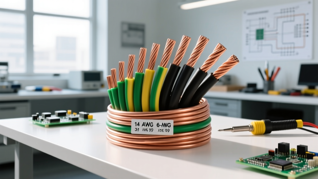
In code terms, a conductor is a material or assembly that permits the flow of electric current. The NEC primarily recognizes copper and aluminum for building wire applications. According to the Copper Development Association, electrical grade copper must meet stringent purity standards (typically 99.9% pure) to ensure predictable resistivity. The conductor's sole job is to transport electrons from the source to the load with minimal voltage drop and heat generation.
The Insulator: Dielectric Barriers and Safety
Conversely, an insulator is a material that prevents or severely restricts the flow of electric current. In the NEC, insulation is not just a coating; it is a highly engineered dielectric barrier rated for specific voltages, temperatures, and environmental conditions. The insulator dictates where the current is allowed to travel and protects both the circuit and the user from shock, short circuits, and arc faults.
Material Physics vs. Code Compliance
While a physicist looks at valence electrons, an electrician or electrical inspector looks at UL listings and ASTM standards. The National Electrical Manufacturers Association (NEMA) and UL categorize these materials based on how they behave under fault conditions and continuous load.
| Characteristic | Conductor (e.g., Copper/Al) | Insulator (e.g., XLPE/PVC) | Governing Standard |
|---|---|---|---|
| Primary Function | Electron flow (Current) | Electron containment (Voltage) | NEC Article 100 |
| Material Base | Metals (Cu, Al, Ag) | Polymers (PVC, XLPE, EPR) | ASTM / UL |
| Thermal Limit Factor | Melting point (>1000°C) | Glass transition / Degradation | NEC Table 310.16 |
| Failure Mode | Fusing / Vaporization | Dielectric breakdown / Melting | UL 44 / UL 83 |
Temperature Ratings and Ampacity Derating
One of the most critical intersections between conductors and insulators is found in NEC Table 310.16. This table dictates the allowable ampacity (current-carrying capacity) of a wire. A common misconception is that the metal conductor limits the ampacity. In reality, the insulator is the limiting factor.
Why the Insulator Fails First
Copper melts at approximately 1,085°C (1,985°F). If we based ampacity solely on the conductor, we could push massive amounts of current through a 12 AWG wire. However, the polymer insulation surrounding the copper will degrade, melt, or catch fire at much lower temperatures.
- 60°C Rating: Standard for older TW and UF cables. The insulation becomes brittle and loses dielectric strength if the conductor exceeds this temperature.
- 75°C Rating: Common for THW and standard terminations. Represents the baseline for most commercial panelboard lugs.
- 90°C Rating: Found in modern THHN and XHHW-2 wires. Allows for higher ampacity and provides a buffer for derating calculations (e.g., adjusting for high ambient temperatures or bundling more than three current-carrying conductors in a raceway).
Therefore, when sizing a wire, you are fundamentally sizing the insulation's ability to dissipate heat without breaking down, rather than the conductor's ability to carry electrons.
Thermoplastic vs. Thermoset Insulators
Understanding how is a conductor different from an insulator also requires knowing how insulators are manufactured. UL standards divide building wire insulation into two primary categories, which drastically affect how the wire handles thermal overloads.
UL 83: Thermoplastic Insulation (THHN/THWN)
Thermoplastic materials like Polyvinyl Chloride (PVC) and Nylon soften and melt when exposed to high heat. THHN (Thermoplastic High Heat-resistant Nylon-coated) is the most common building wire in North America. The nylon jacket provides excellent mechanical protection against abrasion during wire pulling, but the underlying PVC will melt if a sustained overload bypasses the circuit breaker.
UL 44: Thermoset Insulation (XHHW-2)
Thermoset materials like Cross-Linked Polyethylene (XLPE) or Ethylene Propylene Rubber (EPR) undergo a chemical curing process. If exposed to extreme heat, thermoset insulators do not melt; they char or burn. This makes XHHW-2 vastly superior for high-heat environments, solar PV applications, and tight conduit bends where mechanical memory and thermal stability are paramount.
'The insulation system must maintain its dielectric integrity and mechanical properties throughout the expected life of the installation, even when subjected to continuous operation at its rated temperature.' — General principle of UL Wire and Cable Testing Standards.
Dielectric Strength and Voltage Containment
While conductors are rated for current (Amperes), insulators are rated for voltage (Volts). The dielectric strength of an insulator is measured in kilovolts per mil (kV/mil), representing its ability to withstand electrical pressure without allowing current to arc through it.
Standard building wire (THHN/XHHW-2) is rated for 600 Volts. This means the insulator is engineered to contain the electromagnetic field and prevent leakage current at standard residential and commercial voltages (120V, 208V, 277V, 480V). If a 480V circuit experiences a transient voltage spike (surge) that exceeds the dielectric breakdown threshold of the 600V insulation, the insulator fails, resulting in a phase-to-ground or phase-to-phase fault.
The Bare Conductor Exception: Grounding and Bonding
Is an insulator always required? No. NEC Article 250 covers Grounding and Bonding, and it provides a vital exception to the rule. Equipment Grounding Conductors (EGCs) and grounding electrode conductors are frequently installed as bare copper.
Under normal operating conditions, a grounding conductor carries exactly zero current. It only serves as a low-impedance fault path to trip the breaker during a short circuit. Because it is not intended to carry continuous load current, and because it is bonded to the metal enclosure (which acts as a secondary shield), the NEC permits bare copper. This is a prime example of how code application dictates material usage: when the insulator's primary job (containing continuous load heat and voltage) is negated by the circuit's design, the insulator can be safely removed to save cost and improve conduit fill ratios.
Summary: The Symbiotic Relationship
Ultimately, the question of how is a conductor different from an insulator is answered by their symbiotic relationship in electrical design. The conductor provides the highway for electrical energy, governed by its cross-sectional area (circular mils) and resistivity. The insulator provides the guardrails, governed by its thermal rating, dielectric strength, and chemical resistance. An electrical system is only as safe as its weakest insulator, and only as efficient as its most resistive conductor. Adhering to NEC Table 310.16 and UL material standards ensures both operate in perfect harmony.