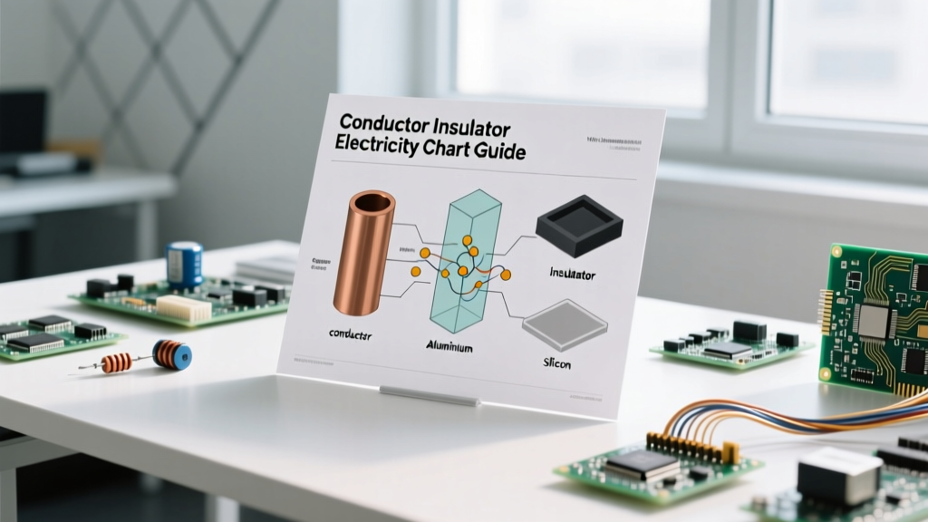

When electrical professionals, engineers, and DIYers ask what is a conductor and insulator of electricity, the answer requires looking past the simple binary of 'metal versus plastic.' At its core, electrical conductivity is dictated by quantum mechanics, specifically the behavior of valence electrons and the energy band gaps within a material's atomic lattice. In the context of wiring, selecting the right conductor and insulator pairing is the difference between a highly efficient, safe circuit and a catastrophic thermal failure.
This comprehensive reference guide breaks down the atomic physics of electrical flow, provides a master chart of material resistivities and dielectric strengths, and explores the real-world engineering decisions that govern modern electrical installations according to the NFPA 70 National Electrical Code (NEC).
The Atomic Divide: Band Theory and Valence Electrons
To truly understand material classification, we must examine the atomic structure. Conductors, primarily metals, possess one to three valence electrons in their outermost shell. These electrons are loosely bound to the nucleus, forming what physicists call a 'sea of free electrons.' When an electromotive force (voltage) is applied, these electrons drift through the lattice, creating current.
Insulators, conversely, have five to eight valence electrons that are tightly bound in full covalent or ionic bonds. In solid-state physics, this is explained by Band Theory. Conductors have overlapping valence and conduction bands, allowing immediate electron flow. Insulators possess a massive 'band gap' (typically greater than 5 electron-volts), meaning it requires an extreme amount of energy to excite an electron into the conduction band. Semiconductors like silicon sit in the middle, with band gaps that can be manipulated via doping or thermal energy.
Master Reference Chart: Resistivity and Dielectric Strength
The table below serves as a quick-reference chart for the most common conductors and insulators used in electrical engineering, detailing their fundamental resistive and dielectric properties at standard room temperature (20°C).
| Material | Classification | Electrical Resistivity (Ω·m at 20°C) | Dielectric Strength (kV/mm) | Primary Application |
|---|---|---|---|---|
| Silver | Conductor | 1.59 × 10⁻⁸ | N/A | High-end audio contacts, aerospace relays |
| Copper (Annealed) | Conductor | 1.68 × 10⁻⁸ | N/A | Standard branch wiring, motor windings |
| Gold | Conductor | 2.44 × 10⁻⁸ | N/A | Corrosion-resistant PCB edge connectors |
| Aluminum (8000 Series) | Conductor | 2.82 × 10⁻⁸ | N/A | Service entrance cables, overhead transmission |
| Tungsten | Conductor | 5.60 × 10⁻⁸ | N/A | Incandescent filaments, high-temp environments |
| PVC (Polyvinyl Chloride) | Insulator | > 10¹⁴ | 15 - 40 | Standard THHN/THWN wire jacketing |
| XLPE (Cross-Linked PE) | Insulator | > 10¹⁶ | 20 - 50 | Medium/High voltage underground cables |
| PTFE (Teflon) | Insulator | > 10¹⁸ | 60 - 100 | Aerospace wiring, high-frequency coax |
| Glass (Fused Silica) | Insulator | 10¹⁰ to 10¹⁴ | 10 - 40 | High-voltage suspension insulators |
Data sourced from the Georgia State University HyperPhysics Resistivity Tables and standard IEEE dielectric testing matrices.
Conductor Selection: Copper vs. Aluminum in the Field
While silver is the most conductive element on earth, its cost prohibits widespread use. Therefore, the electrical industry relies on copper and aluminum. However, understanding the practical differences between the two is critical for wire sizing and safety.
The 61% Conductivity Rule and Sizing Up
Aluminum has roughly 61% of the conductivity of copper by volume. This means that to carry the exact same ampacity (current) without exceeding thermal limits, an aluminum conductor must have a larger cross-sectional area. In practical NEC terms, you must size an aluminum wire approximately two AWG sizes larger than its copper equivalent. For example, a 100-amp subpanel feeder requires #3 AWG Copper, but demands #1 AWG Aluminum.
The Ghost of Aluminum Wiring Past
Many homeowners and electricians harbor a deep distrust of aluminum wiring due to the fire hazards of the 1960s and 70s. This was not a failure of aluminum's conductivity, but a metallurgical flaw. The older 1350-H19 alloy was highly susceptible to thermal creep—it would expand and contract significantly under load, slowly loosening under screw terminals. This led to high-resistance connections, arcing, and fires. Modern building wire uses the AA-8176 (8000-series) alloy, which incorporates iron and copper to drastically reduce creep and improve tensile strength, making it perfectly safe when paired with CO/ALR rated terminations and antioxidant paste (e.g., Noalox).
Expert Insight: Never terminate aluminum wire directly to copper lugs without proper preparation. Galvanic corrosion will occur in the presence of moisture, creating aluminum oxide—a highly resistive insulator that will cause the termination point to overheat and fail.
Insulator Engineering: PVC, XLPE, and Teflon
Answering 'what is an insulator' requires understanding that insulators do not merely stop current; they must also manage heat, resist chemical degradation, and withstand mechanical stress. The Copper Development Association Building Wire Guide highlights how insulation type dictates the allowable ampacity of a wire, even if the copper gauge remains identical.
Thermal Limits and Dielectric Breakdown
- PVC (THHN/THWN): The workhorse of residential and commercial wiring. It is rated for 90°C in dry locations and 75°C in wet locations. However, PVC becomes brittle at extreme cold and releases toxic hydrochloric gas when burned.
- XLPE (XHHW-2): Cross-Linked Polyethylene undergoes a chemical process (using peroxides or silanes) that links polymer chains together. This creates a 3D molecular mesh that will not melt even at 250°C, though its standard operational rating is 90°C wet or dry. It is highly resistant to moisture and corona discharge.
- PTFE (Teflon): Used in specialized applications like aerospace or high-frequency data lines due to its incredibly low dielectric constant (minimizing signal loss) and ability to withstand temperatures up to 260°C.
Real-World Failure Modes: When the Boundary Collapses
Insulators are not perfect. Under extreme conditions, they undergo dielectric breakdown, transitioning suddenly from an insulator to a conductor. In the field, this manifests in several specific failure modes:
- Tracking and Carbonization: When surface moisture and dust accumulate on an insulator (like a ceramic standoff or PVC junction box), micro-currents flow across the surface. This localized heating burns the material, leaving behind a trail of carbon. Since carbon is a conductor, this creates a permanent, low-resistance path that eventually results in a flashover.
- Partial Discharge (Corona): In high-voltage cables (above 2kV), microscopic air voids trapped inside the XLPE insulation can ionize. This 'partial discharge' slowly erodes the insulation from the inside out, creating dendritic (tree-like) channels known as water trees or electrical trees, ultimately leading to catastrophic cable failure.
- UV and Ozone Degradation: Standard PVC is highly susceptible to ultraviolet light. Outdoor runs of THHN wire exposed to direct sunlight will experience photo-oxidation, causing the plasticizer to leach out. The insulation cracks, exposing the bare conductor to ground faults.
Summary: The Symbiosis of the Circuit
Ultimately, a conductor and an insulator are two halves of the same engineering mandate: controlled energy transfer. The conductor provides the path of least resistance for electron flow, while the insulator enforces the boundaries of that path, protecting both the circuit and the environment. Whether you are sizing a 400A service entrance using aluminum alloy or pulling 12 AWG copper THHN through a conduit, respecting the thermal and dielectric limits of both materials is the foundation of electrical safety.