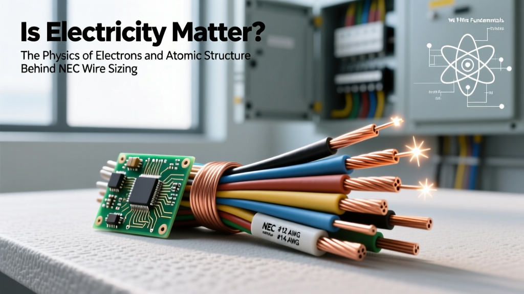

Beyond the Textbook: The True Conductor Insulator Definition
Most DIY electronics guides offer a middle-school summary of electrical materials: conductors let electricity flow, and insulators stop it. While functionally true, this basic conductor insulator definition fails to equip makers, electricians, and engineers with the knowledge needed to troubleshoot complex failures or select the right cable for extreme environments. To truly master wire sizing and electrical fundamentals, we must look past the macro-level behavior and examine the quantum mechanics governing electron mobility, dielectric breakdown thresholds, and thermal degradation.
At its core, the distinction between a conductor and an insulator is not a binary switch but a spectrum defined by atomic structure and energy bands. Understanding this spectrum is the key to preventing catastrophic short circuits, minimizing voltage drop, and ensuring long-term safety in both high-voltage AC wiring and low-voltage DC microcontroller projects.
The Atomic Divide: Free Electrons vs. Bound Valence Shells
The fundamental difference between a conductor and an insulator lies in their electron band structure. In solid-state physics, electrons occupy specific energy levels. The highest energy band that is completely filled with electrons at absolute zero is called the valence band. The next available energy level is the conduction band.
According to Georgia State University's HyperPhysics, the gap between these two bands—the 'band gap'—dictates a material's electrical behavior:
- Conductors: The valence and conduction bands overlap. There is no band gap, meaning electrons require virtually zero additional energy to break free from their parent atoms and drift through the lattice as current. Copper, for instance, has a single electron in its 4s orbital that is loosely bound and easily mobilized by an applied electric field.
- Insulators: The valence band is completely full, and the conduction band is completely empty, separated by a massive band gap (typically greater than 5 electron volts). The electrons are tightly locked in covalent or ionic bonds. Standard room-temperature thermal energy or typical household voltages cannot provide enough energy to bridge this gap.
Quantifying Conductivity: Resistivity and the Band Gap
To move from theoretical physics to practical wire sizing, we must quantify these behaviors using electrical resistivity (measured in Ohm-meters, Ω·m). Resistivity is the intrinsic property that dictates how strongly a material opposes the flow of electric current. Below is a comparative breakdown of materials you will encounter in electrical design and DIY wiring.
| Material | Classification | Resistivity (Ω·m at 20°C) | Band Gap (eV) | Common Application |
|---|---|---|---|---|
| Silver | Conductor | 1.59 × 10⁻⁸ | 0 (Overlap) | High-end audio contacts, aerospace |
| Copper (Annealed) | Conductor | 1.68 × 10⁻⁸ | 0 (Overlap) | Standard THHN building wire, PCB traces |
| Aluminum | Conductor | 2.82 × 10⁻⁸ | 0 (Overlap) | Overhead transmission, heavy feeder cables |
| Silicon | Semiconductor | 6.40 × 10² | 1.11 | Microcontrollers, diodes, transistors |
| Glass | Insulator | 10¹⁰ to 10¹⁴ | 5 to 10 | High-voltage utility insulators |
| PVC (Polyvinyl Chloride) | Insulator | ~10¹⁵ | >6 | Standard wire jacketing, NM-B (Romex) |
| PTFE (Teflon) | Insulator | ~10¹⁸ | >8 | Aerospace wiring, high-temp environments |
Insulator Breakdown: When the Barrier Fails
A critical flaw in the basic conductor insulator definition is the assumption that insulators block current perfectly and indefinitely. In reality, every insulator has a dielectric strength—the maximum electric field it can withstand before it loses its insulating properties and becomes conductive. When the applied voltage exceeds this threshold, the material experiences 'avalanche breakdown,' tearing electrons from their covalent bonds and creating a catastrophic conductive path (an arc or short circuit).
Dielectric strength is typically measured in Volts per mil (V/mil) or kilovolts per millimeter (kV/mm). For context, standard PVC wire insulation boasts a dielectric strength of roughly 400 to 500 V/mil. If you are designing a custom high-voltage power supply or working with mains AC, you must calculate the peak voltage (not just RMS) to ensure your insulation thickness provides an adequate safety margin.
Thermal Degradation and the NEMA Standards
Voltage is not the only enemy of insulation; heat is equally destructive. As temperature rises, the thermal agitation of atoms increases, effectively narrowing the band gap and making it easier for stray electrons to jump into the conduction band. This is why the National Electrical Manufacturers Association (NEMA) strictly categorizes wire insulation by thermal limits.
Expert Insight: Never substitute a 60°C rated TW wire for a 90°C rated THHN wire in a high-ambient-temperature enclosure, even if the gauge is sufficient for the ampacity. The PVC insulation will soften, melt, and eventually suffer dielectric breakdown, leading to an arc fault long before the copper conductor reaches its thermal melting point.
Practical Application: Matching Conductor to Insulator in DIY Wiring
Understanding the physics of conductors and insulators allows you to make informed decisions when selecting wire for specific project constraints. Here is how these definitions translate to real-world cable selection.
Scenario 1: High-Temperature Environments (XLPE vs. PVC)
If you are wiring an automotive engine bay or an industrial control panel where ambient temperatures exceed 75°C, standard PVC insulation will fail. PVC relies on plasticizers to maintain flexibility, which evaporate at high heat, leaving the insulation brittle and prone to cracking. In these scenarios, you must select wires insulated with XLPE (Cross-Linked Polyethylene), such as XHHW-2. The cross-linking process creates a 3D molecular mesh that dramatically increases thermal resistance and dielectric strength without melting, maintaining the insulator's band gap integrity even at 90°C.
Scenario 2: High-Frequency Signals (Skin Effect & PTFE)
In RF (Radio Frequency) circuits or high-speed data lines, the 'conductor' definition gets complicated by the skin effect. At high frequencies, alternating current is forced to the outer edge of the conductor, effectively reducing the cross-sectional area and increasing AC resistance. To combat this, engineers use Litz wire (multiple individually insulated thin strands). The insulator here is often PTFE (Teflon), chosen not just for its massive band gap, but for its exceptionally low dielectric constant, which prevents signal capacitance and high-frequency loss.
Troubleshooting Insulation Failure in the Field
How do you know if an insulator is degrading before it catastrophically fails? You cannot see the band gap narrowing, but you can measure the leakage current. Professional electricians and maintenance engineers use a Megohmmeter (Megger) to test insulation resistance.
Unlike a standard multimeter that uses a 3V to 9V battery to check continuity, a Megger injects a high DC voltage (typically 250V, 500V, or 1000V) into the wire. This high voltage stresses the insulator, simulating peak operational conditions. According to technical resources from Southwire, a healthy 600V-rated cable should exhibit an insulation resistance of well over 100 megohms. If your Megger reads below 1 to 5 megohms, the insulator's molecular structure has been compromised by moisture, heat, or physical abrasion, and the wire must be replaced immediately.
Summary: Engineering with the Spectrum in Mind
The true conductor insulator definition is not a simple binary; it is a complex interplay of quantum band gaps, thermal limits, and dielectric thresholds. By understanding that copper's overlapping bands make it an ideal conductor, and that PVC's massive band gap makes it a reliable—but temperature-sensitive—insulator, you elevate your DIY and electrical work from guesswork to engineered precision. Always match the conductor's ampacity to the load, and equally important, match the insulator's dielectric and thermal ratings to the environment.