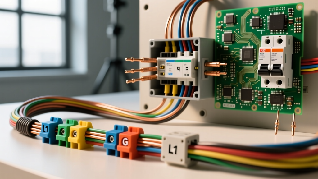

Whether you are wiring a new 240V EV charger, extending a 20A workshop circuit, or troubleshooting a flickering lighting run, selecting the correct wire size is the most critical decision in any electrical project. Undersized conductors lead to catastrophic voltage drop, overheated insulation, and fire hazards. Oversized conductors waste money and make terminations physically difficult.
This quick reference guide cuts through the noise, providing electricians and advanced DIYers with exact American Wire Gauge (AWG) metrics, National Electrical Code (NEC) ampacity rules, and real-world application scenarios. Bookmark this page for immediate job-site reference.
The Core Metrics: Decoding AWG and Circular Mils
The American Wire Gauge system is a logarithmic stepped scale used primarily in North America. Because it is logarithmic, a change of 3 gauge numbers results in a doubling or halving of the wire's cross-sectional area. A change of 10 gauge numbers changes the area by a factor of exactly 10.
Why Smaller Numbers Mean Thicker Wires
Historically, the gauge number represented the number of drawing dies a metal rod had to pass through to reach its final diameter. A wire that required 14 passes (14 AWG) was thinner than a wire that only required 10 passes (10 AWG). Today, we rely on Circular Mils (CM) to measure cross-sectional area, which directly dictates the wire's current-carrying capacity (ampacity).
One circular mil is the area of a circle with a diameter of one mil (one-thousandth of an inch). The formula to calculate the CM of any solid wire is simply the square of its diameter in mils ($CM = d^2$). For stranded wire, you multiply the CM of a single strand by the total number of strands.
Master Wire Size Quick Reference Chart (Copper)
The following table outlines the standard physical dimensions and NEC ampacity ratings for solid and stranded copper conductors. Note: Ampacity values are based on standard conditions and assume no more than three current-carrying conductors in a raceway at an ambient temperature of 30°C (86°F).
| AWG Size | Diameter (Inches) | Area (kcmil) | 60°C Ampacity (NM-B) | 75°C Ampacity (THWN) | 90°C Ampacity (THHN) |
|---|---|---|---|---|---|
| 14 | 0.0641 | 4.11 | 15A | - | - |
| 12 | 0.0808 | 6.53 | 20A | 25A | 30A |
| 10 | 0.1019 | 10.38 | 30A | 35A | 40A |
| 8 | 0.1285 | 16.51 | 40A | 50A | 55A |
| 6 | 0.1620 | 26.24 | 55A | 65A | 75A |
| 4 | 0.2043 | 41.74 | 70A | 85A | 95A |
| 2 | 0.2576 | 66.36 | 95A | 115A | 130A |
| 1/0 | 0.3249 | 105.60 | 125A | 150A | 170A |
Source: Cerrowire Ampacity Charts and NEC Table 310.16.
The Termination Temperature Trap: NEC 110.14(C)
The most common mistake even seasoned DIYers make is using the 90°C column for sizing breakers. According to NFPA 70: National Electrical Code (NEC) section 110.14(C), you must size your conductor based on the lowest temperature rating of any connected device, termination, or conductor.
Most standard residential breakers and receptacles are rated for 75°C, while older devices or specific NM-B (Romex) cable assemblies are limited to 60°C. Therefore, even if you pull 10 AWG THHN (rated 40A at 90°C) through a conduit, if it terminates on a standard residential breaker, you must use the 75°C column (35A) or the 60°C column (30A) depending on the equipment listing. You can use the 90°C column only for derating factors, never for the final base ampacity limit.
Voltage Drop: The Hidden Efficiency Killer
Ampacity charts assume a short run. When wire size extends over long distances, resistance causes voltage to drop. The NEC recommends a maximum voltage drop of 3% for branch circuits and 5% for the combined feeder and branch circuit to ensure reasonable efficiency.
The Quick-Calc Voltage Drop Formula
For single-phase circuits, use this formula to find the maximum one-way length ($L$) in feet before you must increase your wire size:
VD = (2 × K × I × L) / CM
- VD: Voltage Drop (Target: 3.6V for a 120V circuit, 7.2V for a 240V circuit)
- K: Direct Current Constant (12.9 for Copper, 21.2 for Aluminum at 75°C)
- I: Current in Amperes (Use 80% of continuous load or 100% of non-continuous)
- L: One-way length of the wire in feet
- CM: Circular Mils of the conductor
For example, running a 15A continuous load (18A total) on a 120V circuit using 12 AWG Copper (6530 CM) over 100 feet results in a voltage drop of 7.12V (nearly 6%). This exceeds the 3% recommendation, meaning you must step up to 10 AWG or even 8 AWG wire size to maintain equipment health.
Material Matters: Copper vs. Aluminum Sizing
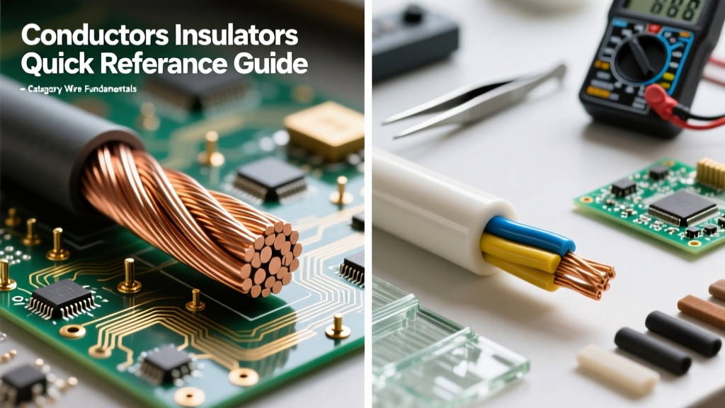
While copper is the undisputed king of residential branch circuits, aluminum is heavily utilized for service entrance cables, subpanel feeders, and heavy commercial feeders due to its lower cost and lighter weight. However, aluminum has a higher coefficient of thermal expansion and lower conductivity.
The Golden Rule: When substituting aluminum for copper, you generally must increase the wire size by two AWG steps to achieve the same ampacity. For instance, a 100A subpanel feeder requires 4 AWG Copper, but demands 2 AWG Aluminum. Always ensure your terminations are explicitly rated for aluminum (marked AL/CU) and apply an antioxidant paste like Noalox to prevent galvanic corrosion and high-resistance arcing.
Real-World Application Scenarios
Scenario A: 50-Amp RV Receptacle (NEMA 14-50)
A common DIY project is installing a NEMA 14-50 receptacle for an RV or EV charger. The breaker is 50A. If you use 6/3 NM-B (Romex) cable, you are bound to the 60°C column, which rates 6 AWG at 55A. This is perfectly acceptable for a 50A breaker. However, if you pull individual THHN conductors in PVC conduit, you can use 8 AWG Copper if the receptacle and breaker are strictly rated for 75°C. If you are unsure of the receptacle rating, default to 6 AWG THHN to guarantee safety and pass inspection.
Scenario B: 20-Amp Dedicated Workshop Circuit
For a 120V, 20A receptacle supplying heavy power tools, 12 AWG Copper is the mandatory minimum. If the workshop is 150 feet from the main panel, voltage drop becomes a factor. Using the formula above, 12 AWG will yield a 4.2% drop at a full 20A load. To protect sensitive tool motors from undervoltage damage, stepping up the wire size to 10 AWG Copper for the long run is the professional choice.
NEC Derating Factors You Cannot Ignore
When bundling multiple circuits in a single conduit, the wires heat each other up. NEC Table 310.15(C)(1) mandates ampacity derating. If you pull four separate 12 AWG THHN circuits (8 current-carrying conductors) through a single 3/4-inch EMT conduit, you must apply an 80% derating factor to the 90°C ampacity column.
- 12 AWG THHN at 90°C = 30A.
- 30A × 0.80 = 24A adjusted ampacity.
- Since 24A is still above the 20A breaker requirement, 12 AWG remains legal. If you had 10 current-carrying conductors (50% derating), 30A × 0.50 = 15A, forcing you to increase your wire size to 10 AWG.
Expert Troubleshooting: Signs of Undersized Wiring
If you are auditing an existing installation, look for these critical failure modes that indicate an improper wire size:
- Warm Faceplates: Receptacles or switches that feel warm to the touch under normal load indicate high resistance, often caused by undersized wires or loose terminations.
- Lights Dimming on Motor Startup: If lights on the same circuit dim when a compressor or vacuum kicks on, the wire size is too small to handle the inrush current without severe voltage sag.
- Discolored Insulation: Brown or brittle insulation near breaker lugs or wire nuts is a definitive sign of thermal degradation caused by exceeding the conductor's ampacity.
Always consult local codes and utilize tools like the Southwire Voltage Drop Calculator to verify your math before pulling wire. Proper wire sizing is not just about passing inspection; it is about ensuring the longevity and safety of the entire electrical ecosystem.