
The Fundamental Divide: How AC Devices Draw Power
When designing circuits for alternating current devices, treating every load as a simple resistor is a critical error that leads to tripped breakers, voltage sag, and premature equipment failure. Unlike direct current (DC) systems where voltage and current remain constant, alternating current (AC) operates on a sinusoidal waveform. This means the interaction between voltage and current is dictated by the physical nature of the load itself.
To properly size conductors and overcurrent protection, we must analyze the phase angle between the voltage and current waveforms. This phase relationship determines the Power Factor (PF) and dictates how much "real" work the device performs versus how much "reactive" power it draws from the grid. Let us break down the primary categories of alternating current devices and compare their electrical behavior, wire sizing requirements, and real-world failure modes.
Categorizing Alternating Current Devices by Load Profile
Resistive Loads (Unity Power Factor)
Resistive devices convert electrical energy directly into heat or light. In these alternating current devices, the voltage and current waveforms are perfectly in phase (Phase Angle = 0°), resulting in a Power Factor of 1.0. Common examples include baseboard heaters (e.g., the Cadet F2502-1500W), incandescent lighting, and toaster ovens.
Wire Sizing Rule: Sizing is straightforward. You calculate the continuous load (operating for 3+ hours) and multiply by 125% per NEC Article 210.20. A 1500W heater on a 120V circuit draws 12.5A. Multiplying by 1.25 yields 15.6A, requiring a minimum 20A breaker and 12 AWG copper wire.
Inductive Loads (Lagging Power Factor & High Inrush)
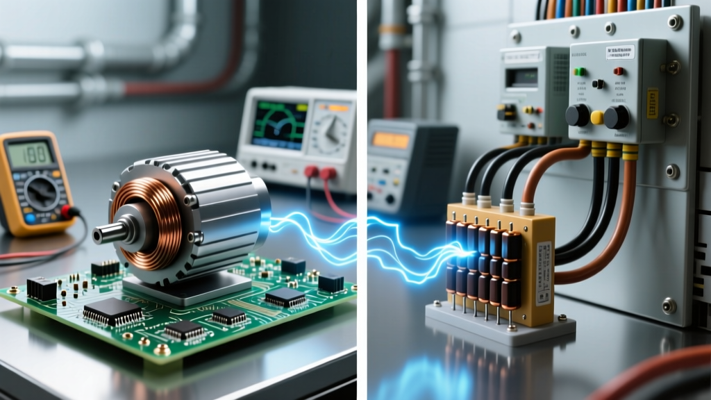
Inductive alternating current devices rely on magnetic fields to operate. This category includes induction motors, transformers, solenoids, and HVAC compressors. Because magnetic fields take time to build and collapse, the current waveform "lags" behind the voltage waveform. This creates a lagging Power Factor (typically 0.75 to 0.90 for industrial motors).
More critically, inductive motors draw massive Locked Rotor Amperage (LRA) during startup—often 5 to 8 times their Full Load Amperage (FLA). For instance, a Baldor-Reliance 5HP, 230V single-phase motor might have an FLA of 28A but an LRA exceeding 160A. This inrush current lasts for a few seconds but severely impacts voltage drop calculations.
Capacitive Loads (Leading Power Factor)
Capacitors store energy in an electric field, causing the current to "lead" the voltage. Standalone capacitive alternating current devices are rare in residential settings; they are primarily used in industrial environments for Power Factor Correction (PFC) banks or within electronic ballasts for fluorescent lighting. While they do not typically dictate main feeder wire sizing, they alter the overall phase angle of the facility's electrical system, reducing the reactive current burden on the utility transformer.
Head-to-Head: Alternating Current Devices Comparison Matrix
The following matrix contrasts the electrical characteristics of the three primary load types, providing a quick reference for circuit design and wire sizing.
| Device Category | Typical Power Factor | Inrush Multiplier (x FLA) | NEC Sizing Rule (Conductors) | Common Failure Mode |
|---|---|---|---|---|
| Resistive (Heaters, Ovens) | 1.0 (Unity) | 1.0x (No Inrush) | 125% of Continuous Load (NEC 210.20) | Thermal runaway, open heating element |
| Inductive (Motors, Compressors) | 0.75 - 0.90 (Lagging) | 5.0x to 8.0x (High LRA) | 125% of FLA (NEC 430.22) | Contactor chatter, insulation melting at lugs |
| Capacitive (PFC Banks, Ballasts) | Leading (Varies) | High transient spike | Sized to capacitor kVAR rating | Dielectric breakdown, harmonic resonance |
| Switching/Non-Linear (VFDs, LEDs) | Distorted (High THD) | Depends on internal caps | 125% + Harmonic derating | Neutral conductor overheating |
Wire Sizing Implications for High-Inrush AC Devices
Calculating Voltage Drop During Motor Startup
When wiring inductive alternating current devices, the primary concern is not just the continuous heat generated by the FLA, but the voltage drop caused by the LRA. According to Fluke's power quality guidelines, excessive voltage drop during startup can cause the magnetic coil in the motor's contactor to drop out, resulting in rapid "chatter" that will destroy the contactor points within minutes.
Consider a 240V, 30A FLA compressor located 100 feet from the panel. If you size the wire strictly for the 125% continuous rule (37.5A), you might choose 8 AWG THHN copper. However, if the LRA is 180A, the voltage drop during startup is calculated as:
VD = (2 x K x I x D) / CM
Where K=12.9 (copper), I=180A, D=100ft, and CM=16,510 (for 8 AWG). The voltage drop is roughly 28V (nearly 12%). If the utility voltage is already sagging at 230V, a 12% drop brings the voltage at the motor down to 202V. Most standard Siemens or Square D contactors will fail to hold the circuit closed below 85% of nominal voltage (204V). To solve this, you must upsize the conductors to 6 AWG or even 4 AWG, not for thermal ampacity, but to maintain startup voltage stability.
Breaker Sizing: NEC Article 430 in Practice
A common DIY mistake is sizing the breaker to the wire ampacity for motor circuits. EC&M outlines that NEC Article 430 separates overload protection (sized at 115-125% of FLA, usually at the motor controller) from short-circuit and ground-fault protection (the branch circuit breaker). For a standard alternating current device like an induction motor, the branch breaker can be sized up to 250% of the FLA to allow the motor to start without tripping the instantaneous magnetic trip mechanism of the breaker.
Real-World Failure Modes: When the Wrong Wire Meets the Wrong Device
Understanding the physics of alternating current devices prevents catastrophic field failures. Here are three specific failure modes encountered when wire sizing ignores load characteristics:
- Harmonic Neutral Overheating: Non-linear alternating current devices (like LED drivers and Variable Frequency Drives) draw current in sharp pulses rather than smooth sine waves. This creates Triplen harmonics (3rd, 9th, 15th) that do not cancel out on the neutral conductor in a 3-phase wye system. The neutral wire can carry more current than the phase wires, leading to melted neutral busbars if not upsized to 200% capacity.
- Skin Effect in Large Feeders: While negligible in standard 12 AWG or 10 AWG residential wiring, the AC skin effect forces current to travel along the outer edge of the conductor in large feeders (e.g., 500 kcmil) powering heavy industrial alternating current devices. This effectively reduces the cross-sectional area, increasing AC resistance compared to DC resistance. Using compact stranded or specialized ACSS (Aluminum Conductor Steel Supported) wire mitigates this.
- Terminal Creep and Thermal Cycling: Inductive loads that start and stop frequently cause massive thermal cycling in the conductors. Aluminum wire, in particular, is prone to "cold creep" under the mechanical pressure of terminal lugs. As the wire heats up during LRA and cools down, the connection loosens, increasing contact resistance and eventually causing an arc fault or fire at the receptacle.
Summary: Matching Conductors to the Load Profile
Designing safe, efficient circuits requires looking beyond the basic wattage formula. Alternating current devices demand a nuanced approach to wire sizing that accounts for power factor, locked rotor amperage, harmonic distortion, and voltage drop limits. Resistive loads require simple thermal ampacity calculations, while inductive and non-linear loads demand rigorous voltage drop analysis and specialized breaker coordination. By respecting the unique electrical signatures of these devices, you ensure long-term reliability, prevent nuisance tripping, and protect your equipment from premature failure.