
The Fundamentals: What Is a Soldering Wick?
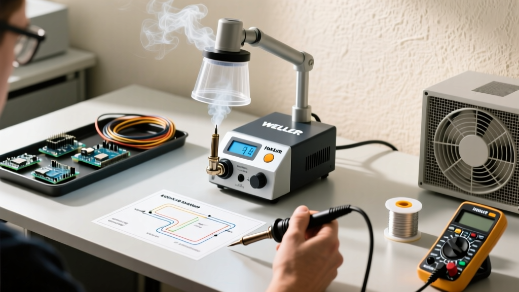
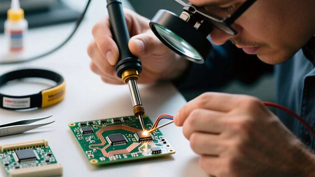
At its core, a soldering wick (commonly referred to as desoldering braid) is a precision consumable tool used to remove molten solder from printed circuit boards (PCBs). It consists of finely braided strands of oxygen-free high conductivity (OFHC) copper that are pre-coated with a specific flux chemistry. When a heated soldering iron tip is applied to the wick placed over a solder joint, the copper rapidly conducts thermal energy into the solder, melting it. Simultaneously, the flux breaks down surface oxides, allowing the molten alloy to be drawn into the microscopic gaps between the copper strands via capillary action.
In the 2026 electronics landscape, where lead-free alloys like SAC305 and SAC405 dominate due to strict RoHS compliance, thermal management during desoldering is more critical than ever. Lead-free solders melt at higher temperatures (217°C–227°C) and exhibit poorer wetting characteristics than legacy Sn63/Pb37 alloys, making high-quality, freshly fluxed wick an absolute necessity for preventing pad delamination on high-Tg FR4 boards.
Anatomy of a Soldering Wick
- Base Material: OFHC Copper. The high purity ensures maximum thermal conductivity and prevents the wick from oxidizing too rapidly under the iron tip.
- Flux Core:
- Rosin Mildly Activated (RMA): Excellent wetting, but requires post-cleaning with isopropyl alcohol (IPA) to prevent long-term corrosion.
- No-Clean: Leaves a minimal, non-corrosive, high-resistivity residue. The industry standard for modern SMD rework.
- Unfluxed: Used in specialized applications where the technician applies their own liquid or tacky flux (e.g., Chip Quik NC191).
- Width Profiles: Wick is categorized by number. #1 (0.025" / 0.6mm) for 0402/0603 SMDs; #2 (0.060" / 1.5mm) for standard SOICs and 0805s; #3 (0.098" / 2.5mm) for large ground pads and through-hole; #4 (0.125" / 3.2mm) for heavy power planes.
Method Comparison Matrix: Wick vs. Pump vs. Hot Air
Understanding what a soldering wick is requires contextualizing it against alternative desoldering methods. Each technique serves a distinct purpose in the rework workflow, governed by IPC-7711/7721 standards for electronic assembly modification.
| Feature | Soldering Wick (Braid) | Desoldering Pump (Solder Sucker) | Hot Air Rework Station |
|---|---|---|---|
| Primary Use Case | SMD pad prep, fine-pitch ICs, bridge removal | Through-hole components, large mechanical joints | BGA, QFN, multi-pin SMD removal |
| Thermal Stress | Moderate (localized to tip contact area) | Low (rapid heat extraction via vacuum) | High (broad area heating, risks nearby components) |
| Pad Flattening | Excellent (leaves pads perfectly flush) | Poor (often leaves solder donuts in vias) | N/A (does not touch pads directly) |
| Cost (2026 Avg) | $5.00 – $9.00 per spool | $15 (Manual) to $235 (Electric) | $120 – $400+ for station |
| Skill Requirement | Medium (requires precise temp & pressure control) | Low (point, melt, and trigger) | High (requires airflow and temp profiling) |
1. Soldering Wick (The Surface Finisher)
Soldering wick is unmatched for surface-level solder removal. When replacing a QFP-64 microcontroller, a manual solder sucker cannot clear the fine 0.5mm pitch pads without risking bridge shorts. Wick pulls the solder completely out of the intermetallic boundary, leaving a flat, oxidized-free surface ready for a new component. Top Market Picks: The Chemtronics Soder-Wick (No-Clean, #2 width, SKU: 80-2-5) remains the gold standard at roughly $7.50 per spool, while the Goot Wick (CP-2015) offers superior capillary draw for Japanese-market lead-free alloys.
2. Desoldering Pumps (The Through-Hole Workhorse)
If you are removing a through-hole electrolytic capacitor or a DIP-28 socket, wick is the wrong tool; it will clog instantly and waste expensive copper braid. Instead, a desoldering pump uses a mechanical spring or electric vacuum to suck away bulk molten solder. The manual Engineer SS-02 ($14.99) features a fluoropolymer nozzle that resists solder adhesion, while the electric Hakko FR-301 ($235.00) provides continuous vacuum extraction for high-volume through-hole teardowns.
3. Hot Air Rework (The Bulk SMD Remover)
Hot air stations (like the Quick 861DW) use convective heat to melt all pins of an SMD component simultaneously, allowing removal with tweezers. While excellent for lifting a chip intact, hot air leaves the PCB pads covered in uneven, oxidized solder blobs. This is where the methods combine: Professionals use hot air to remove the component, and then immediately follow up with a soldering wick to flatten and clean the pads before installing the replacement.
Step-by-Step: How to Use Soldering Wick Without Lifting Pads
According to Adafruit's Excellent Soldering Guide, the most common cause of destroyed PCBs during rework is improper wick technique. Follow this IPC-compliant workflow:
- Match the Width: Select a wick width that matches the pad or trace width. Using a #4 wick on a 0603 pad will draw heat away too slowly and risk scorching the board.
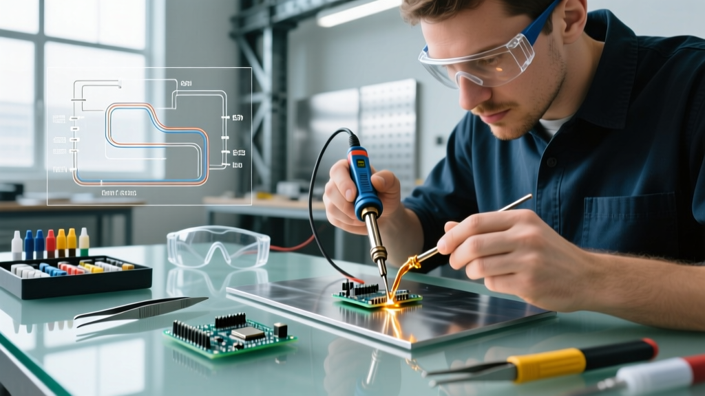
- Profile the Temperature: Set your iron to 350°C for leaded solder and 380°C–390°C for SAC305 lead-free. Use a chisel or bevel tip (e.g., Hakko T18-D24) to maximize surface area contact. Never use a conical (point) tip with wick; the contact area is too small to transfer the necessary thermal mass.
- The "Drag and Lift" Technique: Lay the wick over the target joint. Place the iron tip on top of the wick at a 45-degree angle. Apply zero downward pressure. Let the capillary action and flux do the work. Drag the wick slowly as it turns silver and absorbs the solder.
- Observe the Dwell Time: Never hold the iron on a single pad for more than 3 to 5 seconds. If the solder doesn't flow, remove the iron, let the board cool for 10 seconds, add a drop of liquid tacky flux, and try again.
- Clean the Residue: Snip off the used, silver-colored portion of the wick (do not reuse it; the flux is depleted and copper oxides will ruin your next joint). Clean the PCB pads with 99% IPA and a lint-free swab.
Expert Warning: Never pull the wick away from the board while the solder is cooling. If the molten alloy solidifies while the wick is still in contact with the pad, the copper strands will fuse to the PCB trace. Ripping it off will instantly lift the pad off the fiberglass substrate. Always remove the iron first, then immediately slide the wick away while the joint is still liquid.
Critical Failure Modes and Edge Cases
Even experienced technicians encounter edge cases when desoldering. Understanding these failure modes separates hobbyists from professionals.
Failure Mode 1: Wick Sticking to the Board
Cause: Iron temperature is too low, or the flux has burned off (often caused by using old, oxidized wick that was left exposed to ambient humidity).
Solution: Discard oxidized wick (it will look dark brown or black instead of bright copper). Increase iron temperature by 10°C and apply external liquid flux (e.g., Amtech NC-559-V2-TF) to the joint before reapplying the wick.
Failure Mode 2: Solder Refusal to Wick (The Ground Plane Sink)
Cause: The component pin is connected to a massive internal copper ground plane. The plane acts as an infinite heat sink, preventing the localized joint from reaching the 217°C+ melting point of lead-free solder.
Solution: Switch to a higher wattage iron (minimum 65W–100W) with a heavy thermal mass tip. Alternatively, use a pre-heater (like the APT-8010) set to 120°C to elevate the baseline temperature of the entire PCB, reducing the thermal delta the iron must overcome.
Failure Mode 3: Thermal Shock to MLCCs
Cause: Using wick to clean pads adjacent to Multi-Layer Ceramic Capacitors (MLCCs). The rapid, localized heating followed by IPA cleaning causes severe thermal gradients, leading to micro-cracks in the ceramic dielectric.
Solution: As noted in Electronics Notes Desoldering Techniques, allow the board to cool to room temperature naturally before applying any liquid solvents for cleaning. Never use compressed air to speed up cooling.
Final Verdict: Building Your 2026 Rework Kit
So, what is a soldering wick's true value in the modern workbench? It is not a standalone solution for every desoldering task, but rather the ultimate finishing tool. A properly equipped lab in 2026 requires a synergistic approach: use an Engineer SS-02 pump to evacuate bulk through-hole solder, utilize a hot air station to lift dense SMD chips, and rely on Chemtronics No-Clean Soder-Wick to prepare the pads for flawless re-installation. Mastering capillary desoldering ensures your rework is virtually indistinguishable from factory-original assembly.
For further reading on proper through-hole and SMD rework protocols, refer to the SparkFun Through-Hole Soldering Tutorial, which provides excellent visual baselines for thermal dwell times and flux behavior.