
Decoding the 40-Pin Header: What You Need to Know
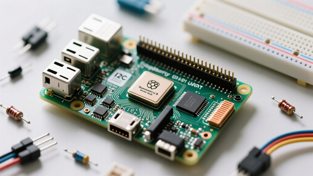
When you first unbox a Raspberry Pi 3 Model B or B+, the two rows of metal pins in the top-left corner can look intimidating. This is the 40-pin GPIO (General Purpose Input/Output) header, and it is the physical bridge between your Pi's Linux brain and the real world of sensors, motors, and LEDs. Understanding the raspberry pi3 pinout is the single most important step for any beginner transitioning from software coding to hardware hacking.
Unlike a microcontroller such as an Arduino, the Raspberry Pi 3 is a full-fledged single-board computer running an operating system. This means its GPIO pins are not designed to handle high currents or 5-volt logic levels. Misunderstanding the pinout can lead to instant, irreversible damage to the Broadcom BCM2837 system-on-chip (SoC). This guide will break down the physical layout, the software mapping, and the critical safety rules you must follow to build reliable DIY electronics projects.
Physical Pin Numbering vs. BCM GPIO Numbering
The most common trap for beginners writing their first Python script is confusing physical pin numbers with Broadcom (BCM) channel numbers. When you look at the Pi with the USB ports facing you and the GPIO header in the top left, Pin 1 is the top-left pin (closest to the HDMI port), and Pin 2 is directly to its right.
- BOARD Numbering: Refers to the physical pin number on the header (1 through 40). This is hardware-agnostic and easy to count with your eyes.
- BCM Numbering: Refers to the Broadcom SoC GPIO channel numbers (e.g., GPIO17, GPIO22). This is how the Linux kernel and the chip's internal architecture actually address the pins.
If you are using the popular RPi.GPIO Python library, you must declare your numbering system at the start of your script using GPIO.setmode(GPIO.BOARD) or GPIO.setmode(GPIO.BCM). Most modern tutorials and the official Raspberry Pi Foundation documentation recommend using BCM numbering, as it aligns with the gpio command-line tools and device tree overlays.
The Raspberry Pi3 Pinout Map: Power, Ground, and GPIO
Not all pins on the header are programmable GPIO pins. The 40-pin header is a mix of power rails, ground connections, and specialized communication interfaces. Below is a structured breakdown of the most critical pins you will use in your beginner projects.
| Function | Physical Pin(s) | BCM GPIO | Beginner Notes |
|---|---|---|---|
| 3.3V Power | 1, 17 | N/A | Max current draw is roughly 50mA. Use for low-power sensors. |
| 5V Power | 2, 4 | N/A | Directly tied to the USB power input. Great for powering servos or relays. |
| Ground (GND) | 6, 9, 14, 20, 25, 30, 34, 39 | N/A | Always required to complete a circuit. Multiple pins provided for convenience. |
| Standard GPIO | e.g., 11, 13, 15 | 17, 27, 22 | Safe for basic digital HIGH/LOW inputs and outputs (3.3V logic). |
| I2C Data (SDA) | 3 | 2 | Includes onboard 1.8kΩ pull-up resistors to 3.3V. |
| I2C Clock (SCL) | 5 | 3 | Used for connecting OLED displays and environmental sensors. |
Communication Protocols Hidden in the Pi3 Pinout
Beyond simple digital on/off states, the raspberry pi3 pinout exposes hardware-level communication buses. Knowing where these live saves you from trying to 'bit-bang' protocols in software, which is notoriously unreliable on a non-real-time OS like Linux.
The Pi 3 UART Quirk: Bluetooth vs. Header
Serial communication (UART) is essential for connecting GPS modules or communicating with an Arduino. On older Pi models, Pins 8 (TXD / GPIO14) and 10 (RXD / GPIO15) were tied to the high-performance hardware UART (/dev/ttyAMA0).
However, the Raspberry Pi 3 introduced an onboard Bluetooth module. To support this, Raspberry Pi engineers routed the hardware UART to the Bluetooth chip, leaving the 'mini-UART' (/dev/ttyS0) connected to the GPIO header. The mini-UART is less stable and its baud rate is tied to the core clock frequency. If you need reliable serial communication on a Pi 3, you must edit your /boot/config.txt file to add dtoverlay=disable-bt, which disables Bluetooth and restores the hardware UART to the GPIO pins.
SPI and I2C Buses
The SPI (Serial Peripheral Interface) bus is located on Pins 19 (MOSI), 21 (MISO), 23 (SCLK), 24 (CE0), and 26 (CE1). It is significantly faster than I2C and is typically used for high-speed devices like TFT LCD screens or RFID readers (like the RC522). I2C, located on Pins 3 and 5, is slower but only requires two wires to daisy-chain up to 127 devices, making it perfect for BME280 temperature sensors or MPU6050 accelerometers.
Critical Safety Rules to Avoid Frying Your Pi 3
The Broadcom BCM2837 chip operates strictly at 3.3V logic. This is the most vital concept to internalize when studying the raspberry pi3 pinout.
WARNING: Never connect a 5V logic output (like those from a standard Arduino Uno or a 5V ultrasonic sensor) directly to a Raspberry Pi 3 GPIO input pin. Doing so will force 5 volts into a 3.3V-tolerant silicon pathway, instantly and permanently destroying the GPIO bank or the entire SoC.
If you must interface 5V components with your Pi 3, use a logic level converter or a simple voltage divider made of resistors to step the 5V signal down to a safe 3.3V before it reaches the Pi's input pin.
Understanding Current Limits
Each GPIO pin can safely source or sink up to 16mA of current. However, the total combined current draw from all GPIO pins simultaneously should not exceed 50mA. If you attempt to power a motor or a high-brightness LED strip directly from the 3.3V GPIO pins, you will trip the Pi's internal polyfuse or burn out the voltage regulator. Always use transistors (like the 2N2222) or MOSFETs to switch high-current loads, using the Pi's GPIO pin only to send the low-current 'signal' to the transistor's base or gate.
Your First Wiring Project: Blinking an LED Safely
Let's apply the pinout knowledge to a real circuit. You want to connect a standard 5mm red LED to Physical Pin 11 (BCM GPIO17). You cannot connect the LED directly between Pin 11 and Ground; you must use a current-limiting resistor to prevent the LED from drawing more than the pin's 16mA limit.
Calculating the Correct Resistor Value
We use Ohm's Law (R = V / I) to find the right resistor. According to resources like Pinout.xyz, Pin 11 outputs 3.3V when HIGH. A standard red LED has a forward voltage drop of about 2.0V and operates safely at 20mA (0.02A). However, we want to limit our draw to a safer 15mA (0.015A) to respect the Pi's total bank limits.
- Voltage across resistor: 3.3V (Source) - 2.0V (LED drop) = 1.3V
- Target Current: 0.015A
- Resistance needed: 1.3V / 0.015A = 86.6 Ohms
Since 86.6Ω is not a standard resistor value, you should round up to the nearest common value: 100Ω. Wiring a 100Ω resistor in series with your LED guarantees your Pi 3 remains safe while delivering plenty of brightness.
Troubleshooting Common Pinout Wiring Mistakes
Even with a perfect wiring diagram, beginners frequently run into hardware bugs. Here is a rapid-response checklist for when your circuit refuses to work:
- I2C Devices Not Showing Up: Did you enable the I2C interface? Run
sudo raspi-config, navigate to 'Interface Options', and enable I2C. Then usei2cdetect -y 1in the terminal to scan the bus. - GPIO Pin Always Reads LOW: You may have configured the pin as an Output in Python, but are trying to read it as an Input. Ensure your
GPIO.setup()matches your physical intention. - Erratic Sensor Readings: The Pi 3 is susceptible to voltage noise if powered by a cheap, unregulated USB phone charger. Ensure your power supply delivers a clean 5V/2.5A. Use a multimeter to check the voltage between Pin 2 (5V) and Pin 6 (GND); if it reads below 4.8V, your Pi is under-voltage and GPIO behavior will become unpredictable.
- SPI Failing: Remember that SPI requires you to connect the MISO (Master In Slave Out) to the Pi's MISO, and MOSI to MOSI. Cross-referencing the physical pinout map is mandatory, as sensor manufacturers often label pins from the sensor's perspective, not the host's.
Mastering the raspberry pi3 pinout is a rite of passage. By respecting the 3.3V logic boundaries, understanding the difference between BOARD and BCM numbering, and properly calculating your current limits, you transform the Pi from a simple desktop computer into a powerhouse for physical computing and IoT innovation.