
Decoding the Raspberry Pi 5 Pinout Diagram for OS Configuration
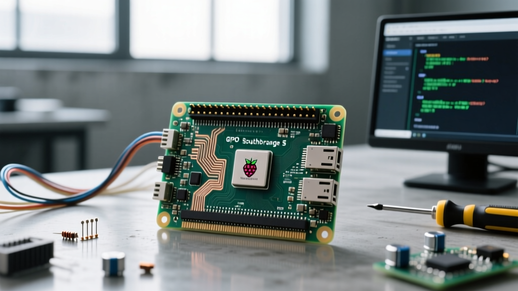
When transitioning from older single-board computers to the latest generation, understanding the physical hardware is only half the battle. The Raspberry Pi 5 pinout diagram looks remarkably familiar at first glance, retaining the standard 40-pin GPIO header that has become the industry standard for SBCs. However, beneath the surface, the architectural shift to the BCM2712 SoC and the custom RP1 southbridge chip has fundamentally altered how the operating system interacts with these pins. For makers, smart home integrators, and embedded engineers, mapping the physical pinout to the OS device tree is the critical first step in any project.
In this comprehensive OS and distribution guide, we will bridge the gap between the physical Pinout.xyz interactive header guide and the software-level configurations required in Raspberry Pi OS (Bookworm), Ubuntu, and Home Assistant OS. We will cover the deprecation of legacy sysfs interfaces, the new RP1 device tree overlays, and exact CLI commands to verify your GPIO states.
Physical Pinout vs. OS Device Tree Mapping
The physical layout of the 40-pin header remains compatible with Pi 4 HATs and add-on boards, but the OS-level addressing has shifted. Because the GPIOs are no longer routed directly through the main application processor, the OS must communicate with the RP1 chip via a PCIe 2.0 x1 link to toggle pin states or read I2C/SPI buses.
| Physical Pin | BCM / GPIO | Primary Function | Pi 5 OS / RP1 Mapping Note |
|---|---|---|---|
| 1 | 3.3V | Power | Up to 3A total across all 3.3V pins (regulated from 5V). |
| 2 | 5V | Power | Direct from USB-C PD; supports up to 5A with 27W official PSU. |
| 3 | GPIO 2 | I2C1 SDA | Requires dtparam=i2c_arm=on in config.txt. |
| 4 | 5V | Power | Same as Pin 2. |
| 5 | GPIO 3 | I2C1 SCL | Features hardware pull-ups on the Pi 5 board. |
| 6 | GND | Ground | Common ground for RP1 and BCM2712. |
| 7 | GPIO 4 | GPCLK0 | Clock routing now handled by RP1 PLLs. |
| 8 | GPIO 14 | UART0 TXD | Default console serial; disable via raspi-config for raw UART. |
| 9 | GND | Ground | Essential for stable SPI/I2C signaling. |
| 10 | GPIO 15 | UART0 RXD | Must disable serial console to use as general RX. |
For a complete breakdown of all 40 pins, refer to the Raspberry Pi Official Hardware Documentation. The most critical takeaway for OS configuration is that while the BCM numbering scheme (e.g., GPIO 2, GPIO 14) is preserved in user-space libraries for backward compatibility, the kernel device tree addresses these via the RP1 PCI endpoint.
The RP1 Southbridge: Why Pi 5 GPIO Configuration Changed
To effectively configure your OS, you must understand the RP1. In the Pi 4, the BCM2711 SoC handled USB, Ethernet, and GPIO directly. In the Pi 5, the BCM2712 focuses purely on high-performance compute and memory, offloading peripheral management to the RP1.
From an OS perspective, this means that GPIOs are technically PCIe endpoints. When you load a device tree overlay (dtoverlay) in your boot configuration, the OS is instructing the kernel to route specific RP1 pins to hardware controllers like SPI0 or I2C1. This architecture drastically improves USB and Ethernet throughput but introduces slight microsecond-level latency differences in raw GPIO bit-banging compared to the Pi 4. For 99% of Home Assistant and DIY electronics projects, this latency is imperceptible, but it dictates why older, hardcoded kernel modules from the Buster/Bullseye eras will fail to compile or load on Pi 5.
Enabling I2C, SPI, and UART in Raspberry Pi OS (Bookworm)
Raspberry Pi OS Bookworm introduced significant changes to how services and hardware interfaces are managed. The legacy raspi-gpio tool and the sysfs interface (/sys/class/gpio) are officially deprecated.
Step 1: Using raspi-config for Standard Buses
For standard I2C and SPI enablement, the interactive tool remains the safest route to ensure the correct RP1 overlays are applied:
- Open your terminal and run
sudo raspi-config. - Navigate to Interface Options.
- Select I2C or SPI and choose Yes to enable the ARM interface.
- Reboot the system to allow the kernel to load the RP1 device tree nodes.
Step 2: Manual config.txt Overlay Injection
If you are building a headless OS image or using a minimal distribution, you can manually edit the boot configuration. On the Pi 5, this file is located at /boot/firmware/config.txt.
# Enable I2C and SPI on RP1
dtparam=i2c_arm=on
dtparam=spi=on

# Enable specific UART mapping (disable serial console first)
dtoverlay=disable-bt
enable_uart=1
Modern CLI Tools: Mastering libgpiod and pinctrl
Because the sysfs interface is deprecated, writing bash scripts that echo values into /sys/class/gpio/export will no longer work reliably on Bookworm or modern Ubuntu Server distributions. The OS now relies on the libgpiod character device API.
To verify your Raspberry Pi 5 pinout mappings from the command line, install the modern toolset:
sudo apt install gpiodOnce installed, you can inspect the state of any pin mapped in your diagram. For example, to check the status of Physical Pin 7 (BCM GPIO 4):
gpioinfo | grep "GPIO4"
gpioset gpiochip0 4=1  # Set pin HIGH
gpioset gpiochip0 4=0  # Set pin LOW
Additionally, Raspberry Pi provides the pinctrl utility, which is specifically optimized for the RP1 and BCM2712 architecture. Running pinctrl get 14 will instantly tell you if the UART TXD pin is correctly muxed for serial communication or if it has been accidentally reassigned to a generic input by a conflicting overlay.
Troubleshooting GPIO Mapping Errors in Home Assistant OS
Running Home Assistant OS (HAOS) on a Pi 5 is a premier smart home setup, but HAOS is a heavily containerized, immutable operating system. You cannot simply run apt install gpiod or edit config.txt from the terminal easily.
If you are trying to integrate physical relays or sensors using the Home Assistant GPIO Integration, you must ensure the underlying host OS has exposed the RP1 GPIO character devices to the Docker containers.
Expert Tip: In HAOS, the
config.txtfile is accessible via the Samba add-on or by mounting the boot partition on a separate PC. Ensure thatdtparam=i2c_arm=onis present if you are using I2C-based sensors (like BME280 or BH1750) mapped to Pins 3 and 5. Without this, the Home Assistant I2C integration will fail to poll the bus, returning 'Device not found' errors despite correct physical wiring.
Furthermore, ensure your Home Assistant Core container is running with the necessary privileges to access /dev/gpiochip0. Recent updates to HAOS have improved native RP1 support, but legacy HATs designed for the Pi 3/4 may require manual EEPROM flashing or custom overlay compilation to be recognized by the Pi 5's PCIe-based southbridge.
Power Pin Distribution and OS-Level Monitoring
The Raspberry Pi 5 pinout diagram features robust power delivery, but OS-level monitoring is required to prevent brownouts. The 5V pins (2 and 4) are directly tied to the USB-C PD input. If you use the official 27W USB-C PD power supply, the board can negotiate 5V/5A, allowing you to draw significantly more current through the GPIO header for external relays or LED strips.
The 3.3V rail (Pin 1) is generated by a high-efficiency buck converter on the Pi 5, capable of supplying much more current than the Pi 4's linear regulator. However, you can monitor the PMIC (Power Management IC) and RP1 voltage states directly from the OS using the vcgencmd tool:
vcgencmd pmic_read_adc 3V3
vcgencmd pmic_read_adc 5V
Integrating these CLI commands into a Node-RED dashboard or Telegraf/Grafana stack allows you to monitor real-time voltage drops on the GPIO header, ensuring your external circuits are not pulling the RP1 logic levels out of specification.
Summary: Best Practices for Pi 5 Pinout Projects
Successfully utilizing the Raspberry Pi 5 pinout diagram requires shifting your mindset from legacy SoC mapping to the modern RP1 southbridge architecture. Always rely on libgpiod and pinctrl for user-space GPIO manipulation, use raspi-config to safely inject device tree overlays, and remember that while the physical 40-pin header is backward compatible, the OS-level drivers demand updated, Bookworm-compatible libraries. By aligning your physical wiring with these OS-specific configurations, your SBC projects will achieve maximum stability and performance.