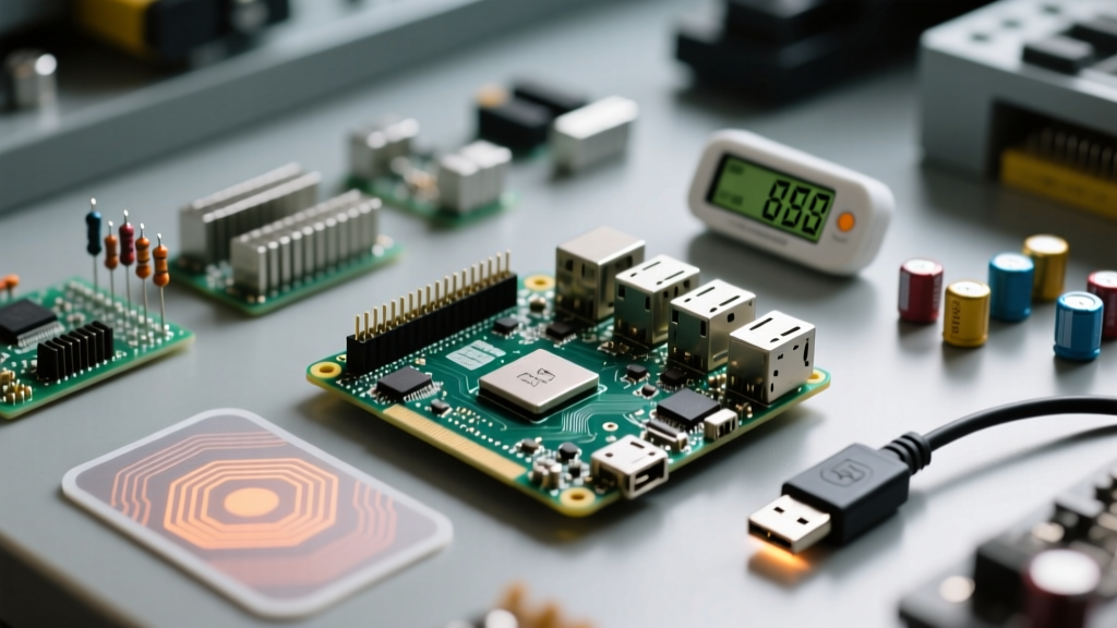
The Raspberry Pi 5 retains the industry-standard 40-pin GPIO header, but the underlying architecture has fundamentally changed. Unlike the Pi 4, where the BCM2711 SoC handled GPIO directly, the Pi 5 routes all header I/O through the dedicated RP1 southbridge chip. This means the physical Raspberry Pi 5 pinout diagram remains backward-compatible for basic wiring, but logic levels, pull-up states, and multiplexing behaviors are now governed by the RP1. All GPIO pins operate at 3.3V logic; injecting 5V into any data pin will instantly destroy the RP1 chip.
The Complete Raspberry Pi 5 Pinout Diagram
Below is the definitive 40-pin reference table. Read it left-to-right, matching the physical pins on your board. The BCM column is the software identifier you will use in Python (via gpiozero or RPi.GPIO), while the Physical column is the literal pin number stamped on the board silkscreen.
| Phys | Function / Name | BCM | Phys | Function / Name | BCM |
|---|---|---|---|---|---|
| 1 | 3V3 Power | - | 2 | 5V Power | - |
| 3 | SDA1 (I2C) | 2 | 4 | 5V Power | - |
| 5 | SCL1 (I2C) | 3 | 6 | Ground | - |
| 7 | GPCLK0 | 4 | 8 | TXD (UART) | 14 |
| 9 | Ground | - | 10 | RXD (UART) | 15 |
| 11 | GPIO 17 | 17 | 12 | PCM_CLK / PWM0 | 18 |
| 13 | GPIO 27 | 27 | 14 | Ground | - |
| 15 | GPIO 22 | 22 | 16 | GPIO 23 | 23 |
| 17 | 3V3 Power | - | 18 | GPIO 24 | 24 |
| 19 | MOSI (SPI0) | 10 | 20 | Ground | - |
| 21 | MISO (SPI0) | 9 | 22 | GPIO 25 | 25 |
| 23 | SCLK (SPI0) | 11 | 24 | CE0 (SPI0) | 8 |
| 25 | Ground | - | 26 | CE1 (SPI0) | 7 |
| 27 | ID_SD (I2C ID) | 0 | 28 | ID_SC (I2C ID) | 1 |
| 29 | GPIO 5 | 5 | 30 | Ground | - |
| 31 | GPIO 6 | 6 | 32 | GPIO 12 / PWM0 | 12 |
| 33 | GPIO 13 / PWM1 | 13 | 34 | Ground | - |
| 35 | GPIO 19 | 19 | 36 | GPIO 16 | 16 |
| 37 | GPIO 26 | 26 | 38 | GPIO 20 | 20 |
| 39 | Ground | - | 40 | GPIO 21 | 21 |
Pinout Standards: BCM vs. Physical vs. WiringPi
In home wiring, you navigate regional standards like NEC (US) versus IEC (EU). In the Raspberry Pi ecosystem, the equivalent "regional standards" are the three competing pin-numbering schemes. Using the wrong standard in your code will result in toggling the wrong physical pin, potentially shorting a 3.3V output to a 5V input.
- BCM (Broadcom SOC Channel): This maps to the internal RP1/BCM2712 register numbers. For example, Physical Pin 3 is BCM 2. The official
gpiozerolibrary defaults to BCM. If you are reading a C++ or Python tutorial from the last five years, it is almost certainly using BCM. - Physical (BOARD): This is the literal 1-40 pin count on the header. Physical Pin 3 is simply "Pin 3". This is the safest standard for beginners wiring up HATs or ribbon cables, as it requires zero mental translation from the board silkscreen to the breadboard.
- WiringPi: An older, deprecated standard created by Gordon Henderson. It assigned its own arbitrary numbers to pins (e.g., Physical Pin 3 was WiringPi 8). The original WiringPi library does not natively support the Pi 5's RP1 chip. If you see a tutorial referencing WiringPi pin numbers, discard it and find a modern BCM equivalent.
Rows People Get Wrong (and How to Avoid Bricking Your Pi 5)
The 40-pin header is unforgiving. Unlike microcontrollers with robust clamping diodes, the RP1 southbridge on the Pi 5 is highly sensitive to overvoltage. Here are the specific rows and pin groups that cause the most hardware failures on the bench.
1. The Power Rails: Pins 1, 2, and 4
Pin 1 outputs a strict 3.3V reference, limited to roughly 50mA total across all 3.3V draws. Pins 2 and 4 output 5V, directly tied to the USB-C PD input. The mistake: Backfeeding 5V into a sensor's VCC and accidentally routing its 5V logic output into a Pi 5 BCM GPIO. The fix: Always use a logic level shifter (like the TXB0108 or BSS138 MOSFET circuit) when interfacing 5V Arduino-style sensors with the Pi 5.
2. The I2C Bus: Pins 3 and 5 (BCM 2 and 3)
These are your primary I2C data (SDA) and clock (SCL) lines. The mistake: Adding external 10k pull-up resistors to 5V because a generic Arduino tutorial told you to. The Pi 5 already has 1.8kΩ pull-up resistors to 3.3V physically soldered onto the board for these specific pins. The fix: Never add external pull-ups to Pins 3 and 5. If your I2C device requires 5V pull-ups, use the secondary I2C bus (BCM 0 and 1 on Pins 27/28) or a dedicated I2C isolator chip.
3. The UART Console: Pins 8 and 10 (BCM 14 and 15)
These are the TX and RX lines for the primary serial console. The mistake: Crossing TX to TX and RX to RX, or connecting a 5V USB-to-Serial adapter (like the PL2303) directly. The fix: Always cross the lines (Pi TX to Adapter RX, Pi RX to Adapter TX) and ensure your USB-to-Serial adapter is explicitly a 3.3V logic model (like those based on the CP2102 or FT232RL configured for 3.3V).
4. The EEPROM ID Pins: Pins 27 and 28 (BCM 0 and 1)
These are reserved for HAT (Hardware Attached on Top) identification. The mistake: Using them as standard GPIO outputs. The fix: Leave them alone unless you are designing a custom HAT and need to program the EEPROM. The Pi 5 firmware queries these pins at boot; pulling them low or high unpredictably can cause boot delays or HAT misidentification.
Safe Interpretation When Silkscreen is Faded or Missing
On older boards, or boards that have spent years in a dusty enclosure, the tiny white silkscreen numbers next to the GPIO header can wear off. Guessing pin 1 by looking at the USB port orientation is a gamble that will fry your board. Use these three deterministic methods to identify your pins safely.
- The Square Pad Rule (Visual): Flip the board over or look closely at the solder joints on the underside of the header. Pin 1 is always the square solder pad. All other pins (2 through 40) have perfectly round solder pads. Once you locate the square pad, you can map the entire 40-pin grid using the table above.
- The
pinoutCLI Tool (Software): If your Pi 5 is booted into Raspberry Pi OS, open the terminal and typepinout. This built-in utility (part of thegpiozeropackage) will print an ASCII-art diagram of the exact pinout to your console, including the board revision and RP1 chip status. This is the fastest way to verify your mental model before making physical connections. - Multimeter Voltage Mapping (Electrical): If the board is powered but you cannot read the screen or silkscreen, set your multimeter to DC Voltage. Place the black probe on the metal shield of the USB-C port (a known ground). Probe the top-left and top-right pins. The pin reading ~5.0V to 5.1V is Pin 2. The pin reading ~3.3V is Pin 1. Warning: Only probe the two top-row power pins to establish orientation; do not blindly probe data pins with a multimeter, as the probe tip can slip and short adjacent pins.
For authoritative, up-to-date schematics and RP1 multiplexing tables, always refer to the Raspberry Pi Official Documentation. For quick visual checks on the bench, the community-maintained Pinout.xyz interactive diagram remains the gold standard for verifying alternate pin functions (like PCM and DPI) that aren't listed in basic tutorials.