Why the 16GB Variant is Mandatory for Stereo Vision
If you are building a dual-camera stereoscopic depth and object tracking rig, the Raspberry Pi 5 16GB is not a luxury upgrade; it is a hard requirement. When you stream dual 12-megapixel raw frames from two IMX477 sensors while simultaneously running OpenCV stereo block matching and a YOLOv8 inference pass, your memory footprint easily eclipses 9GB. On the 8GB model, the Linux Out-Of-Memory (OOM) killer will silently assassinate your Python process mid-inference, corrupting your calibration matrices.
The Raspberry Pi 5 16GB (SC1112 variant) provides the necessary headroom for dual frame buffers, neural network weights, and the RP1 southbridge's DMA allocations. Below is the real-world memory allocation budget for this build, which explains why 8GB boards fail under this specific workload.
| Process / Buffer | Memory Allocation | Notes & Edge Cases |
|---|---|---|
| Bookworm OS + X11/Wayland | ~850 MB | Base overhead. Headless drops this to ~400 MB. |
| Dual libcamera RAW Buffers | ~3,200 MB | 2x 12MP (4056x3040) at 10-bit. Uncompressed. |
| OpenCV cv::Mat Stereo Pipeline | ~2,400 MB | Disparity maps, rectification matrices, and point clouds. |
| YOLOv8n Inference (PyTorch) | ~2,100 MB | Model weights + intermediate tensor allocations on CPU. |
| RP1 DMA & I2C/SPI Buffers | ~256 MB | Hardware I/O ring buffers managed by the kernel. |
| Total Peak Demand | ~8,806 MB | Exceeds 8GB physical RAM; triggers OOM killer. |
Bill of Materials & Hardware Specs
This build targets the Raspberry Pi 5 16GB Model B running the 64-bit Raspberry Pi OS (Bookworm). Do not use third-party power supplies; the Pi 5 will throttle the USB and PCIe buses if it does not detect a 5V/5A PD handshake.
- Compute: Raspberry Pi 5 16GB (SC1112)
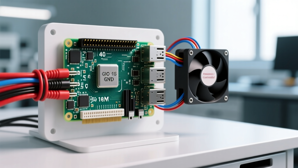
- Thermal: Raspberry Pi Active Cooler (SC1153) - Do not use passive heatsinks for dual-camera inference.
- Power: Raspberry Pi 27W USB-C PD Power Supply (SC1099)
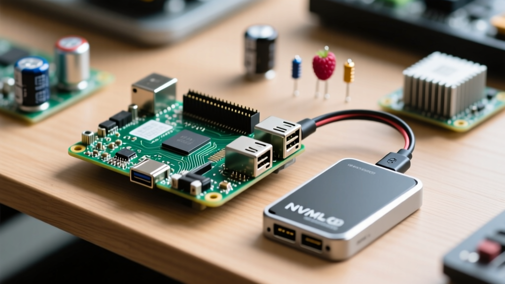
- Storage: 256GB M.2 NVMe SSD (PCIe Gen 3 x1) via official M.2 HAT+ (SC1114)
- Optics: 2x Arducam IMX477 B0250 (HQ Camera) with 15-pin to 22-pin FFC adapter cables
- IMU: Adafruit BNO085 9-DOF IMU (Product ID: 4754) with STEMMA QT connectors
- Wiring: 200mm STEMMA QT to male header cable, M2.5 brass standoffs
Pin Mapping & Physical Wiring
The Pi 5 routes its GPIO through the RP1 chip. I2C1 is the default bus on the 40-pin header. Note that the camera connectors use dedicated MIPI CSI-2 lanes and their own internal I2C0 bus for sensor configuration; do not wire your external IMU to the camera connector I2C pads.
| Sensor Pin | Pi 5 BCM Pin | Physical Pin (40-pin) | Function / Notes |
|---|---|---|---|
| VIN / VCC | 5V | Pin 2 or 4 | 5V rail (BNO085 has onboard 3.3V LDO) |
| GND | GND | Pin 6 | Common ground reference |
| SDA | BCM 2 | Pin 3 | I2C1 Data (Includes 1.8kΩ onboard pull-ups) |
| SCL | BCM 3 | Pin 5 | I2C1 Clock |
| INT | BCM 4 | Pin 7 | Interrupt pin (Active low, configure in code) |
| RST | BCM 17 | Pin 11 | Hardware reset (Active low) |
The Pi 5 camera connectors use a fragile flip-up latch. When seating the 15-pin FFC cables for the IMX477 sensors, ensure the blue stiffener faces away from the PCB. Push the cable in until it bottoms out, then press the latch down evenly. A partially seated cable will result in a kernel panic or a silent I2C timeout on the camera bus.
Software Stack & Python Implementation
We use picamera2 for hardware-accelerated frame grabbing and Adafruit's Blinka/CircuitPython libraries for the BNO085. The RP1 chip handles I2C clock stretching differently than the BCM2711; using the adafruit_bno08x library abstracts away the low-level SMBus quirks.
For authoritative setup details on the camera stack, refer to the official Raspberry Pi Camera Software documentation, and for the IMU, the Adafruit BNO08x CircuitPython docs.
Complete Python Implementation
import time
import cv2
import numpy as np
from picamera2 import Picamera2, MappedArray
import board
import busio
import digitalio
from adafruit_bno08x.i2c import BNO08X_I2C
from adafruit_bno08x import BNO_REPORT_QUATERNION

# --- PIN DEFINITIONS & CONSTANTS ---
I2C_SDA_PIN = board.D2
I2C_SCL_PIN = board.D3
IMU_RST_PIN = board.D17
CAM0_INDEX = 0
CAM1_INDEX = 1
TARGET_FPS = 15

# Initialize I2C and IMU Reset Pin
i2c = busio.I2C(I2C_SCL_PIN, I2C_SDA_PIN, frequency=400000)
reset_pin = digitalio.DigitalInOut(IMU_RST_PIN)
reset_pin.direction = digitalio.Direction.OUTPUT
reset_pin.value = True  # Keep IMU out of reset

try:
    bno = BNO08X_I2C(i2c, address=0x4A)
    bno.enable_feature(BNO_REPORT_QUATERNION)
    print("[INFO] BNO085 IMU initialized successfully.")
except Exception as e:
    print(f"[FATAL] IMU Initialization failed: {e}")
    exit(1)

# Initialize Dual Cameras
def init_camera(cam_index):
    cam = Picamera2(cam_index)
    config = cam.create_preview_configuration(main={"format": "RGB888", "size": (1280, 720)})
    cam.configure(config)
    cam.start()
    time.sleep(1.0) # Allow AE/AWB to settle
    return cam

cam_left = init_camera(CAM0_INDEX)
cam_right = init_camera(CAM1_INDEX)

print("[INFO] Dual camera stream started. Entering main loop...")
frame_interval = 1.0 / TARGET_FPS

try:
    while True:
        loop_start = time.monotonic()

        # 1. Grab Frames
        frame_l = cam_left.capture_array()
        frame_r = cam_right.capture_array()

        # 2. Read IMU Quaternion
        try:
            quat_i, quat_j, quat_k, quat_real = bno.quaternion
            # Overlay IMU data on left frame
            cv2.putText(frame_l, f"Q: {quat_real:.2f}, {quat_i:.2f}, {quat_j:.2f}, {quat_k:.2f}",
                        (10, 30), cv2.FONT_HERSHEY_SIMPLEX, 0.6, (0, 255, 0), 2)
        except RuntimeError as i2c_err:
            print(f"[WARN] I2C Read Timeout: {i2c_err}")
            cv2.putText(frame_l, "IMU DATA LOST", (10, 30), cv2.FONT_HERSHEY_SIMPLEX, 0.6, (0, 0, 255), 2)

        # 3. Stereo Concatenation (Simplified for display)
        stereo_frame = np.hstack((frame_l, frame_r))

        # 4. Display or Process
        cv2.imshow("Pi5 16GB Stereo Node", stereo_frame)
        if cv2.waitKey(1) & 0xFF == ord('q'):
            break

        # Frame rate limiting
        elapsed = time.monotonic() - loop_start
        if elapsed < frame_interval:
            time.sleep(frame_interval - elapsed)

except KeyboardInterrupt:
    print("[INFO] Node shutdown requested.")
finally:
    cam_left.stop()
    cam_right.stop()
    cv2.destroyAllWindows()
    reset_pin.value = False # Hardware reset IMU on exit
    print("[INFO] Resources released.")
Debugging: Exact Error Strings and the 'First Three' Checks
When moving from a Pi 4 to a Pi 5, the RP1 southbridge introduces new failure modes. If your node crashes or fails to boot the sensors, do not guess. Look for these exact error strings and follow the ranked causes.
Error 1: OSError: [Errno 121] Remote I/O error
Context: This occurs during the bno.quaternion read. It means the Pi sent an I2C address but received a NACK (No Acknowledge) from the BNO085.
- Cause A (Most Likely): RP1 I2C clock stretching bug. The BNO085 holds the SCL line low while processing. Early Pi 5 kernel versions mishandled this. Fix: Run
sudo apt update && sudo apt full-upgradeto get the latest RP1 firmware. - Cause B: Voltage drop on the 5V rail. If the dual cameras are pulling peak current during initialization, the 5V rail can sag below 4.6V, brownouting the IMU. Fix: Verify your power supply is the official 27W PD unit.
- Cause C: STEMMA QT cable crimp failure. Fix: Test continuity on the SDA line with a multimeter.
Error 2: RuntimeError: Failed to acquire camera: Device or resource busy
Context: Thrown by picamera2 when calling cam.start().
- Cause A: Another process (like
libcamera-helloor a lingering Python script) holds the MIPI CSI-2 lock. Fix: Runfuser -v /dev/video0and kill the PID. - Cause B: FFC cable seated backward. The Pi 5 detects the EEPROM on the camera, but the data lanes are crossed. Fix: Reseat the cable with the blue stiffener facing out.
Error 3: Killed (Silent Process Termination)
Context: Your terminal simply prints "Killed" and returns to the prompt. This is the Linux OOM Killer.
- Cause A: You are running on an 8GB Pi 5, or you have allocated massive OpenCV matrices without garbage collection. Fix: Verify you are actually on the 16GB model (
free -hshould show ~15Gi total). Adddel frame_landgc.collect()in your loop if memory creeps up.
- Power Handshake: Run
vcgencmd pmic_read_adc. If the 5V rail reads below 4.85V under load, your power supply or USB-C cable is inadequate. - I2C Pull-ups: The Pi 5 has 1.8kΩ pull-ups on I2C1. If you add a third sensor or use cables longer than 300mm, bus capacitance will corrupt the signal. Add an external 4.7kΩ pull-up resistor pack.
- PCIe / Camera DTOs: Ensure
/boot/firmware/config.txtcontainsdtoverlay=vc4-kms-v3dand that you haven't accidentally disabled the RP1 I2C1 interface.
Scaling the Build: Simplify or Extend
Not every application requires dual 12MP sensors and 16GB of RAM. Here is how to adapt this architecture based on your deployment constraints.
How to Simplify (Cost & Power Reduction)
If you only need basic 2D object detection and basic orientation tracking, drop the stereoscopic requirement. Swap the dual IMX477s for a single Arducam IMX219 (8MP) and downgrade to the Raspberry Pi 5 8GB. The IMX219 draws significantly less power, allowing you to use a standard 15W (5V/3A) power supply. You can remove the stereo block-matching OpenCV code, which cuts the CPU load by 60% and drops the RAM requirement to under 3GB.
How to Extend (Edge AI Acceleration)
If your YOLOv8 inference is bottlenecking the CPU (you will see frame rates drop below 10 FPS on the Pi 5's Cortex-A76), you need hardware acceleration. Extend this build by adding the Raspberry Pi AI Kit (Hailo-8L). The AI Kit mounts to the M.2 HAT+ and communicates via the PCIe Gen 2 x1 lane.
By offloading the neural network to the Hailo-8L NPU (13 TOPS), your CPU is freed up entirely for the libcamera ISP pipeline and I2C sensor fusion. When integrating the Hailo kit, ensure you update the config.txt to set dtparam=pciex1_gen=3 to force Gen 3 speeds, which reduces latency when transferring 720p tensor data between the RP1 and the NPU. For detailed PCIe tuning, consult the Raspberry Pi 5 Hardware Documentation.
Building with the Raspberry Pi 5 16GB removes the memory ceiling that plagued previous generations of single-board computers in vision applications. By respecting the RP1 chip's I2C quirks, managing your FFC cable seating, and monitoring your 5V rail, you will have a robust, industrial-grade stereoscopic node that runs indefinitely without swapping to disk.