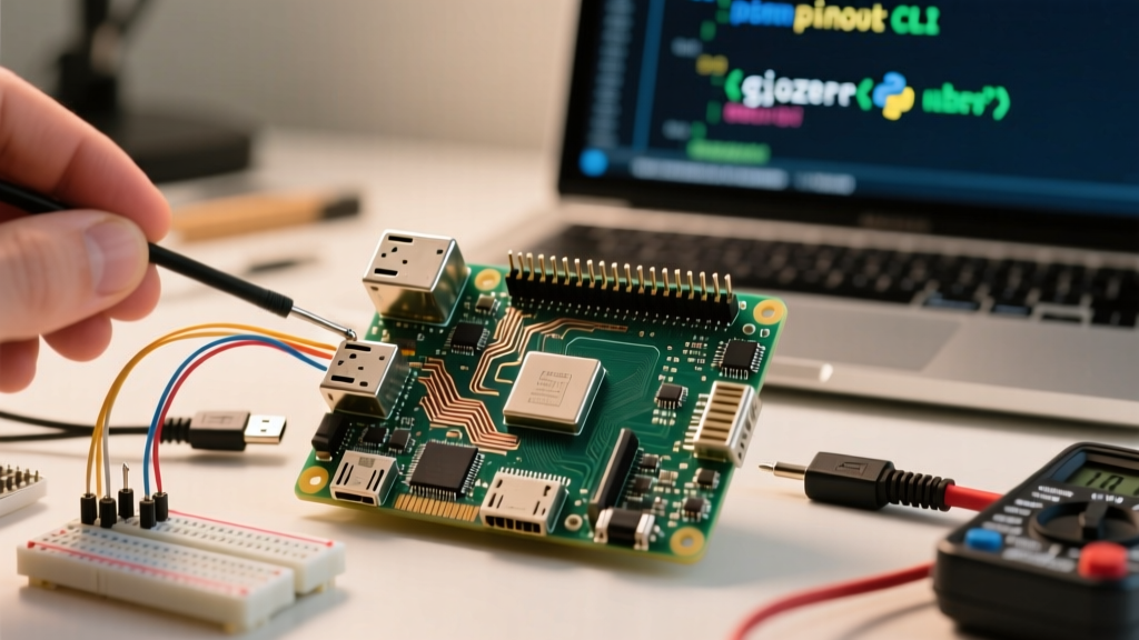
The Raspberry Pi 3 (Model B and B+) uses a standard 40-pin GPIO header operating strictly at 3.3V logic. Pin 1 is the 3.3V power rail located closest to the SD card slot. Always use BCM (Broadcom chip) numbering in your Python/C code, and physical BOARD numbering when tracing wires on the bench.
The Complete Pi 3 GPIO Pinout Reference
The table below maps every physical pin on the 40-pin header to its Broadcom (BCM) GPIO number, primary function, and voltage domain. Read this table by matching the physical pin number (1-40) to your ribbon cable or multimeter probes.
| Pin (Board) | BCM | Name | Primary Function | Voltage / Type |
|---|---|---|---|---|
| 1 | - | 3V3 | 3.3V Power Rail | 3.3V Power |
| 2 | - | 5V | 5V Power Rail | 5V Power |
| 3 | 2 | SDA1 | I2C Data | 3.3V (1.8k Pull-up) |
| 4 | - | 5V | 5V Power Rail | 5V Power |
| 5 | 3 | SCL1 | I2C Clock | 3.3V (1.8k Pull-up) |
| 6 | - | GND | Ground | 0V |
| 7 | 4 | GPCLK0 | General GPIO / Clock | 3.3V Logic |
| 8 | 14 | TXD | UART Transmit | 3.3V Logic |
| 9 | - | GND | Ground | 0V |
| 10 | 15 | RXD | UART Receive | 3.3V Logic |
| 11 | 17 | GPIO17 | General GPIO | 3.3V Logic |
| 12 | 18 | PWM0 | Hardware PWM / GPIO | 3.3V Logic |
| 13 | 27 | GPIO27 | General GPIO | 3.3V Logic |
| 14 | - | GND | Ground | 0V |
| 15 | 22 | GPIO22 | General GPIO | 3.3V Logic |
| 16 | 23 | GPIO23 | General GPIO | 3.3V Logic |
| 17 | - | 3V3 | 3.3V Power Rail | 3.3V Power |
| 18 | 24 | GPIO24 | General GPIO | 3.3V Logic |
| 19 | 10 | MOSI | SPI0 Master Out | 3.3V Logic |
| 20 | - | GND | Ground | 0V |
| 21 | 9 | MISO | SPI0 Master In | 3.3V Logic |
| 22 | 25 | GPIO25 | General GPIO | 3.3V Logic |
| 23 | 11 | SCLK | SPI0 Clock | 3.3V Logic |
| 24 | 8 | CE0 | SPI0 Chip Select 0 | 3.3V Logic |
| 25 | - | GND | Ground | 0V |
| 26 | 7 | CE1 | SPI0 Chip Select 1 | 3.3V Logic |
| 27 | - | ID_SD | HAT EEPROM I2C Data | 3.3V (Reserved) |
| 28 | - | ID_SC | HAT EEPROM I2C Clock | 3.3V (Reserved) |
| 29 | 5 | GPIO5 | General GPIO | 3.3V Logic |
| 30 | - | GND | Ground | 0V |
| 31 | 6 | GPIO6 | General GPIO | 3.3V Logic |
| 32 | 12 | PWM0 | Hardware PWM / GPIO | 3.3V Logic |
| 33 | 13 | PWM1 | Hardware PWM / GPIO | 3.3V Logic |
| 34 | - | GND | Ground | 0V |
| 35 | 19 | MISO | SPI1 / General GPIO | 3.3V Logic |
| 36 | 16 | CE2 | SPI1 CS / General GPIO | 3.3V Logic |
| 37 | 26 | GPIO26 | General GPIO | 3.3V Logic |
| 38 | 20 | MOSI | SPI1 / General GPIO | 3.3V Logic |
| 39 | - | GND | Ground | 0V |
| 40 | 21 | SCLK | SPI1 / General GPIO | 3.3V Logic |
For official hardware specifications and alternative multiplexing functions, always cross-reference the Raspberry Pi Official GPIO Documentation.
Rows People Get Wrong (and How to Avoid Bricking Your Pi)
Unlike the Arduino Uno (ATmega328P), the Broadcom BCM2837 SoC on the Pi 3 has an absolute maximum GPIO voltage of 3.3V. Feeding 5V into any logic pin (like BCM 4 or BCM 17) will permanently destroy the pin and potentially fry the entire SoC.
When wiring up a new project, these are the specific rows and pins that cause the most hardware failures:
- Pins 1 (3.3V) and 2 (5V): Swapping these is a classic breadboard mistake. If you backfeed 5V into the 3.3V rail, you will bypass the onboard voltage regulator and instantly kill the SoC and the WiFi/Bluetooth chip, which run on the 3.3V rail.
- Pins 27 & 28 (ID_SD / ID_SC): These are strictly reserved for the HAT (Hardware Attached on Top) identification EEPROM. They are connected to an internal I2C bus used during boot. Do not use them for general-purpose I2C sensors; use Pins 3 and 5 (BCM 2 and 3) instead.
- Pins 3 & 5 (BCM 2 & 3): These I2C lines have physical 1.8kΩ pull-up resistors hardwired to the 3.3V rail on the Pi's PCB. If you connect a 5V I2C device here without a bidirectional logic level shifter, the 5V device will pull the Pi's 3.3V rail high through the internal pull-ups, causing logic errors or silicon damage.
- Missing Common Ground: When powering external relays or LED strips from a separate 5V or 12V supply, you must connect the external supply's GND to one of the Pi's GND pins (6, 9, 14, 20, 25, 30, 34, or 39). Without a shared ground reference, your GPIO control signals will float and behave erratically.
Wiring Color Standards: Pi HATs vs. IEC vs. NEC
Color coding wires prevents catastrophic mistakes, but the "correct" colors depend entirely on which standard you are following. Mixing up DC electronics colors with AC mains colors is a common hazard when wiring Pi-controlled relay boards to household loads.
| Standard / Context | Power / Hot / Signal | Ground / Neutral / Return | Notes & Application |
|---|---|---|---|
| Standard DC / Breadboard | Red (5V), Orange (3.3V), Yellow/Blue (Signal) | Black (GND) | Universal hobbyist standard. Use red strictly for 5V and orange for 3.3V to avoid Pi SoC damage. |
| Raspberry Pi HAT Spec | Red (5V) | Black (GND) | The official Pi HAT design guide mandates specific EEPROM wiring but generally follows standard DC colors for power delivery. |
| IEC 60446 (EU/UK AC Mains) | Brown (Line/Hot) | Blue (Neutral), Green/Yellow (Earth) | Used when wiring the AC side of a relay controlled by the Pi. Never use Brown/Blue for DC GPIO signals. |
| NEC (US/Canada AC Mains) | Black (Hot) | White (Neutral), Green/Bare (Earth) | US standard. Black is HOT in AC, but BLACK is GND in standard DC electronics. This overlap causes severe confusion. |
The Golden Rule: Never use black wire for a GPIO signal, and never use red/blue/brown wires for AC mains switching on a relay board. Keep your AC wiring (Brown/Blue/Green-Yellow) physically separated from your DC GPIO wiring (Red/Orange/Black) by at least 2 inches, or use a physical barrier.
Safe Interpretation When Markings Are Faded or Missing
In educational labs, industrial control panels, or heavily used workshop Pis, the silkscreen text on the PCB next to the GPIO header often wears off. Guessing pin 1 by eye is a reliable way to short the 5V rail to ground and blow the main polyfuse or PMIC.
If your Pi 3 board lacks clear markings, follow this safe verification protocol before connecting any external circuits:
- Identify Pin 1 by Physical Landmarks: Pin 1 is always the pin closest to the SD card slot and the USB ports. On most Pi 3 boards, the PCB pad for Pin 1 is square, while all other pins are circular. Some revisions also feature a tiny white triangle silkscreened on the PCB pointing to Pin 1.
- Power the Pi and Verify with a Multimeter: Boot the Pi via its micro-USB or USB-C power port. Set your digital multimeter to DC Volts (20V range).
- Establish a Known Ground: Place your black (common) probe against the metal shielding of the USB ports or the Ethernet jack. This is tied directly to the system ground.
- Probe the Suspected Power Rails: Touch your red probe to the suspected Pin 1. It should read 3.2V to 3.3V. Move to the adjacent pin (suspected Pin 2). It should read 5.0V to 5.2V. If you read 5V on the first pin and 3.3V on the second, you are looking at the board upside down.
- Verify Logic Pins Safely: If you need to find a specific GPIO (like BCM 14 / TXD), write a simple Python script to toggle it high (`GPIO.output(14, GPIO.HIGH)`), then probe the suspected pin with your multimeter. A reading of ~3.3V confirms the BCM mapping.
For deeper dives into standard wiring color codes across different electrical domains, All About Circuits provides an excellent reference guide that bridges the gap between low-voltage DC and high-voltage AC standards.
By treating the Pi 3 GPIO header as a strict 3.3V environment, respecting the reserved HAT pins, and maintaining disciplined color-coding across your DC and AC boundaries, you will eliminate 95% of the hardware failures common in embedded Raspberry Pi projects.