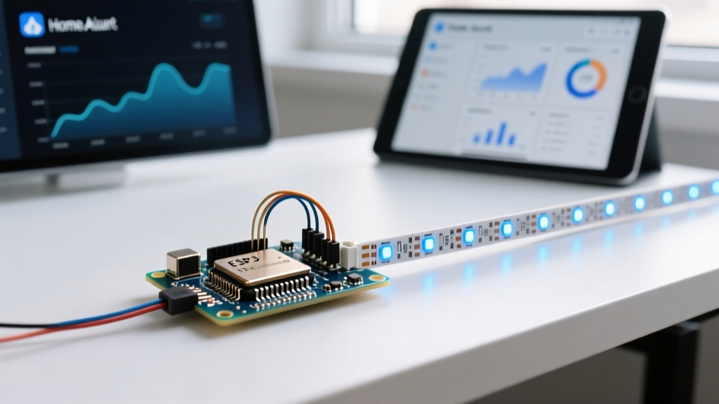
The UART full form is Universal Asynchronous Receiver-Transmitter. It refers to the hardware circuit—or the firmware emulation of it—that translates data between parallel and serial forms. Unlike synchronous protocols that rely on a shared clock line, UART transmits data asynchronously, embedding timing information directly into the data stream via start and stop bits. If you are connecting a GPS module to a Raspberry Pi, linking an ESP32 to an Arduino, or debugging a 3D printer mainboard, you are using UART.
The Physical Layer: Wiring, Levels, and Pull-Ups
UART is a point-to-point protocol requiring a minimum of three connections: TX (Transmit), RX (Receive), and GND (Ground). The golden rule of UART wiring is that the TX pin of Device A must connect to the RX pin of Device B, and vice versa. Never connect TX to TX or RX to RX.
The most common way makers destroy microcontrollers is by directly wiring a 5V Arduino TX pin to a 3.3V ESP32 RX pin. Standard CMOS logic tolerates almost zero overvoltage. You must use a logic level shifter (like a BSS138 bidirectional module or a CD4050 non-inverting buffer) or, in a pinch, a simple resistor voltage divider (e.g., 1kΩ series, 2kΩ to ground) on the 5V TX line to drop it to a safe ~3.3V for the receiver.
Do UART Lines Need Pull-Up Resistors?
No. This is a frequent point of confusion for those migrating from I2C. I2C uses an open-drain architecture, meaning devices can only pull the line low and rely on external pull-up resistors to bring it high. Standard UART uses a push-pull output stage. The microcontroller's UART peripheral actively drives the line both high (to VCC) and low (to GND). Adding 4.7kΩ pull-up resistors to standard UART lines is unnecessary and can actually cause excessive current draw and signal ringing on longer wire runs.
Bus Mechanics and Protocol Comparison
Choosing the right serial bus depends entirely on your constraints regarding distance, speed, and device count. Below is a direct comparison of the three primary maker protocols.
| Feature | UART | I2C | SPI |
|---|---|---|---|
| Wires Required | 2 (TX, RX) + GND | 2 (SDA, SCL) + GND | 4 (MOSI, MISO, SCK, CS) + GND |
| Typical Speed | 9600 bps to 1 Mbps | 100 kHz to 3.4 MHz | 10 MHz to 50+ MHz |
| Addressing | None (Point-to-Point) | 7-bit or 10-bit hardware | None (Individual Chip Select lines) |
| Max Distance | ~50 ft (at 9600 baud) | ~3 ft (without bus buffers) | ~3 ft (highly capacitance-limited) |
| Device Count | 1 per TX/RX pair | Up to 127 per bus | 1 per CS pin (bus sharing possible) |
Decision Framework: Choose UART when you need to communicate over longer distances at low speeds (like a GPS receiver or a cellular modem) or when debugging via a PC. Choose I2C when you have many low-speed sensors on a single board and want to save GPIO pins. Choose SPI when you need high throughput, such as driving an LCD display or reading high-sample-rate ADCs.
Minimal Working Exchange: ESP32 to Arduino Uno
Let's build a minimal working exchange where an ESP32 sends a sensor payload to an Arduino Uno. We will use Hardware Serial 2 on the ESP32 and SoftwareSerial on the Uno to keep the Uno's hardware UART free for USB debugging.
Wiring Table
| ESP32 Pin | Arduino Uno Pin | Notes |
|---|---|---|
| GND | GND | Common ground is mandatory. |
| GPIO 17 (TX2) | Pin 10 (Software RX) | ESP32 is 3.3V, Uno is 5V. This line is safe (3.3V into 5V is read as HIGH). |
| GPIO 16 (RX2) | Pin 11 (Software TX) | Warning: Use a voltage divider here to drop the Uno's 5V TX down to 3.3V. |
ESP32 Code (Sender)
// ESP32 Sender using HardwareSerial 2
#define RXD2 16
#define TXD2 17

void setup() {
  // Initialize Serial2 at 115200 baud, 8 data bits, no parity, 1 stop bit
  Serial2.begin(115200, SERIAL_8N1, RXD2, TXD2);
}

void loop() {
  int sensorVal = analogRead(34); // Read a mock sensor on GPIO 34
  Serial2.print("SENSOR:");
  Serial2.println(sensorVal);
  delay(1000);
}
Arduino Uno Code (Receiver)
// Arduino Uno Receiver using SoftwareSerial
#include <SoftwareSerial.h>

// RX on pin 10, TX on pin 11
SoftwareSerial mySerial(10, 11);

void setup() {
  Serial.begin(115200); // USB debug monitor
  mySerial.begin(115200); // UART link to ESP32
}

void loop() {
  if (mySerial.available()) {
    String payload = mySerial.readStringUntil('\n');
    Serial.print("Received from ESP32: ");
    Serial.println(payload);
  }
}
Sniffing and Debugging the Serial Bus
When your serial monitor outputs garbage characters (often called mojibake), you are almost certainly dealing with a baud rate mismatch or a wiring fault. Here is how to systematically debug the bus.
- Verify the Common Ground: If you only connect TX and RX, the voltage reference floats. The receiver will interpret noise as data. Always connect GND to GND.
- Check for Baud Mismatch: If the sender transmits at 115200 baud but the receiver listens at 9600 baud, the receiver will sample the bits at the wrong times, yielding random ASCII characters. Ensure both
.begin()calls use the exact same integer. - Sniff with a Logic Analyzer: A $15 USB logic analyzer (like a Saleae clone running Sigrok/PulseView) is the ultimate UART debugging tool. Connect the probe to the TX line, set the trigger to the falling edge (the start bit), and let the software decode the hex/ASCII payload.
If you are reverse-engineering an unknown device and don't know its baud rate, probe the TX line with an oscilloscope. Look for the start bit, which is always a logic LOW. Measure the time width of that single low pulse. Baud rate is simply the inverse of that time.
Example: If the narrowest low pulse measures 8.68 µs (0.00000868 seconds), the math is 1 / 0.00000868 = 115,207. You can safely assume the device is communicating at 115200 baud. If the pulse is ~104 µs, it's 9600 baud.
For quick bench tests without a scope, a cheap USB-to-TTL adapter (based on the CH340, CP2102, or FT232RL chips) allows you to bridge the unknown TX line directly to your PC's serial terminal (like PuTTY or CoolTerm) to cycle through standard baud rates until the text becomes legible. For deeper protocol specifications, refer to the SparkFun Serial Communication guide or the Espressif ESP32 UART API documentation.
Frequently Asked Questions
What does the UART full form stand for in microcontrollers?
The UART full form is Universal Asynchronous Receiver-Transmitter. In modern microcontrollers like the ATmega328P (Arduino Uno) or the ESP32, the UART is rarely a standalone physical chip. Instead, it is a dedicated hardware peripheral block integrated directly into the silicon die, managed via memory-mapped registers that handle the shifting of parallel bytes into serial bitstreams automatically.
Does UART need pull-up resistors like I2C?
No, standard UART does not require pull-up resistors. UART lines are driven by push-pull output stages, meaning the microcontroller actively drives the voltage high to VCC and low to GND. I2C requires pull-ups because it uses open-drain outputs. Adding pull-ups to a standard UART bus is redundant and can degrade signal integrity on longer cable runs by altering the RC time constant of the trace.
Why is my UART outputting garbage characters?
Garbage characters (mojibake) are almost always caused by a baud rate mismatch between the sender and receiver. If the sender is configured for 115200 baud and the receiver is set to 9600 baud, the receiver's sampling clock will misalign with the incoming bits, interpreting noise as valid ASCII. Secondary causes include a missing common ground connection, a swapped TX/RX pair, or attempting to read a 3.3V logic signal with a 5V threshold that isn't being met cleanly.
Can UART communicate over long distances?
Standard logic-level UART (0V to 3.3V/5V) is highly susceptible to electromagnetic interference and capacitance, limiting reliable runs to about 2 to 3 feet on a breadboard or PCB. However, if you pass the UART signals through a physical layer transceiver like an RS-232 driver (e.g., MAX232) or an RS-485 differential driver (e.g., MAX485), you can extend UART communication to 50 feet (RS-232) or over 4,000 feet (RS-485) by increasing the voltage swing or using differential signaling to reject common-mode noise.