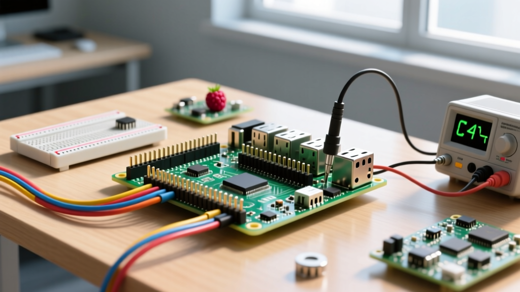

The 40-Pin GPIO Header: Pinout, Power, and Logic Levels
The Raspberry Pi 40-pin GPIO header is the physical bridge between your single-board computer and the external world. Whether you are using a Raspberry Pi 4 Model B or the newer Pi 5, the physical footprint and primary functions of these Raspberry Pi header pins remain largely consistent. However, misinterpreting the pinout is the leading cause of fried logic circuits and bus communication failures.
The most critical rule of the header is voltage: all GPIO data pins operate at 3.3V logic. Feeding 5V into any GPIO pin (like BCM 17 or BCM 27) will permanently damage the SoC. The header does provide 5V and 3.3V power rails, alongside multiple ground (GND) pins to minimize return-path inductance.
Essential Pin Mapping Reference
Below is the spec-sheet table for the most commonly used pins in embedded sensor projects. We map the Physical Pin (1-40) to the Broadcom (BCM) GPIO number, which is the standard used by modern Python libraries like gpiozero.
| Physical Pin | BCM GPIO | Function | Typical Usage |
|---|---|---|---|
| 1 | N/A | 3.3V Power | Powering 3.3V sensors (max 50mA draw) |
| 2 | N/A | 5V Power | Powering 5V modules, relays, displays |
| 3 | 2 (SDA1) | I2C Data | I2C communication (requires pull-up) |
| 5 | 3 (SCL1) | I2C Clock | I2C communication (requires pull-up) |
| 6 | N/A | Ground | Circuit common / return path |
| 11 | 17 | GPIO | Digital input (buttons) or output (LEDs) |
| 19 | 10 (MOSI) | SPI MOSI | SPI Master Out Slave In |
| 21 | 9 (MISO) | SPI MISO | SPI Master In Slave Out |
| 23 | 11 (SCLK) | SPI Clock | SPI Clock signal |
For a complete interactive map of every alternate function (UART, PWM, PCM), consult the definitive Pinout.xyz Raspberry Pi GPIO reference.
Project Build: I2C OLED Dashboard with Button Interrupt
To demonstrate proper header pin wiring and bus debugging, we will build a hardware dashboard. This project targets the Raspberry Pi 4 Model B (4GB variant) running Raspberry Pi OS (Bookworm or Bullseye), utilizing an I2C OLED display and a tactile push button.
Parts List
- Board: Raspberry Pi 4 Model B (4GB or 8GB)
- Display: 0.96-inch 128x64 OLED (SSD1306 driver, I2C interface, 4-pin variant)
- Input: 6x6mm Tactile push button (momentary, normally open)
- Passives: 10kΩ through-hole resistor (for button pull-up)
- Wiring: Female-to-female jumper wires (20cm, 28 AWG stranded)
Wiring the Header Pins
- OLED VCC: Connect to Physical Pin 1 (3.3V). Note: Many SSD1306 modules tolerate 5V, but using 3.3V keeps the I2C data lines safely within the Pi's 3.3V logic threshold.
- OLED GND: Connect to Physical Pin 6 (Ground).
- OLED SCL: Connect to Physical Pin 5 (BCM 3).
- OLED SDA: Connect to Physical Pin 3 (BCM 2).
- Button Leg 1: Connect to Physical Pin 11 (BCM 17).
- Button Leg 2: Connect to Physical Pin 6 (Ground).
- Pull-up Resistor: Solder or breadboard the 10kΩ resistor between BCM 17 (Button Leg 1) and 3.3V (Physical Pin 1) to prevent floating input states.
Python Implementation: SMBus2 and GPIOZero
The following Python script uses gpiozero for robust button debouncing and smbus2 for raw I2C header communication. This avoids heavy dependencies while demonstrating exact error handling for bus faults.
import time
import sys
from gpiozero import Button
from smbus2 import SMBus

# --- PIN & BUS DEFINITIONS ---
# Physical Pin 11 = BCM 17
BUTTON_PIN = 17
# I2C Bus 1 corresponds to Physical Pins 3 (SDA) and 5 (SCL)
I2C_BUS = 1
# Standard SSD1306 I2C Address
OLED_ADDR = 0x3C

def init_oled(bus):
    """Send basic initialization commands to SSD1306 via I2C header."""
    # Command byte 0x00, followed by display OFF, then ON
    commands = [
        0xAE,  # Display OFF
        0x20, 0x00,  # Set Memory Addressing Mode (Horizontal)
        0xA8, 0x3F,  # Set Multiplex Ratio (64)
        0xAF   # Display ON
    ]
    for cmd in commands:
        bus.write_byte(OLED_ADDR, cmd)
    print('OLED initialized successfully via header pins 3 & 5.')

def handle_button_press():
    print('Button pressed on BCM 17! Toggling display state.')
    # In a full app, you would invert the display buffer here

def main():
    # Initialize button with internal/external pull-up logic
    # pull_up=True assumes the pin is pulled to 3.3V and button connects to GND
    btn = Button(BUTTON_PIN, pull_up=True, bounce_time=0.05)
    btn.when_pressed = handle_button_press

    try:
        with SMBus(I2C_BUS) as bus:
            init_oled(bus)
            print('System running. Press button on Physical Pin 11.')

            # Keep main thread alive to catch interrupts
            while True:
                time.sleep(1)

    except FileNotFoundError as e:
        print(f'FATAL: I2C bus not found. Did you enable I2C in raspi-config?')
        print(f'Exact error: {e}')
        sys.exit(1)
    except OSError as e:
        print(f'FATAL: I2C communication failed on header pins.')
        print(f'Exact error: {e}')
        sys.exit(1)
    except KeyboardInterrupt:
        print('\nShutdown requested by user.')
    finally:
        print('Cleaning up resources.')

if __name__ == '__main__':
    main()
Debugging Header Mistakes: Fixing I/O Errors
When working with Raspberry Pi header pins, hardware misconfigurations manifest as specific OS-level exceptions. The most notorious of these is the I2C bus failure.
The Error: OSError: [Errno 121] Remote I/O error
If your terminal outputs OSError: [Errno 121] Remote I/O error when executing bus.write_byte(), the kernel successfully opened the I2C device file, but the hardware ACK (acknowledge) signal was never received on the SDA line.
The First Three Things to Check
- Verify SDA/SCL Orientation: The most common mistake is swapping Physical Pin 3 (SDA) and Physical Pin 5 (SCL). I2C is not symmetric. Swap the jumper wires on the header and reboot.
- Check I2C Interface Status: Run
sudo raspi-config, navigate to Interface Options > I2C, and ensure it is enabled. Alternatively, runls /dev/i2c*in the terminal. If/dev/i2c-1is missing, the kernel overlay is not loaded. - Scan the Bus for ACK: Execute
i2cdetect -y 1. If the output shows--at address3c, the Pi is not seeing the device. This indicates a missing ground connection (Physical Pin 6) or missing pull-up resistors on the SDA/SCL lines.
1. Swapped SDA/SCL header pins (60% of cases).
2. Missing common ground between Pi and sensor (25% of cases).
3. I2C address mismatch (e.g., sensor is at 0x3D, code expects 0x3C) (10% of cases).
4. Bus capacitance too high due to excessively long jumper wires (>30cm) (5% of cases).
For deeper hardware diagnostics, the official Raspberry Pi hardware documentation details the internal 1.8kΩ pull-up resistors present on the Pi's I2C header pins, which usually negate the need for external resistors on short wire runs.
Frequently Asked Questions About Raspberry Pi Header Pins
Are Raspberry Pi header pins 5V tolerant?
No. The GPIO data pins (BCM 0 through BCM 27) on all modern Raspberry Pi models are strictly 3.3V tolerant. The internal silicon operates at lower voltages, and the 3.3V rail is regulated down for the I/O pads. If you connect a 5V Arduino output or a 5V ultrasonic sensor directly to a Pi header pin, you will forward-bias the internal ESD protection diodes, causing excessive current flow that will permanently fry the SoC. Always use a logic level converter (like the BSS138 MOSFET bi-directional board) or a simple resistor voltage divider when interfacing 5V logic with the Pi header.
How do I identify pin 1 on the 40-pin header?
Pin 1 is always located in the top-left corner of the header when the Raspberry Pi is oriented with the USB/Ethernet ports facing toward you and the GPIO header on the top right. To confirm visually without relying on orientation: look at the solder joints on the underside of the board. The pad for Pin 1 is square, while all other pads (Pins 2 through 40) are perfectly round. Additionally, most official boards feature a tiny silkscreen triangle or the text 'P1' printed on the PCB mask directly adjacent to this pin.
Can I solder directly to the Raspberry Pi header pins without a HAT?
Yes, you can solder directly to the header pins, but it requires careful thermal management. The pins are typically brass with a gold flash plating, soldered through plated-through holes (PTH) on the PCB. If you are attaching a custom perfboard or direct wires, use a temperature-controlled soldering iron set to 320°C-350°C with rosin-core (flux) solder. Apply heat to the pad and pin simultaneously for no more than 2-3 seconds per joint to avoid delaminating the PCB traces or melting the plastic spacer holding the header block together. For production or repeated prototyping, soldering a low-profile female header socket to your custom board and plugging it onto the Pi's male pins is vastly superior and prevents mechanical stress on the Pi's PCB.


