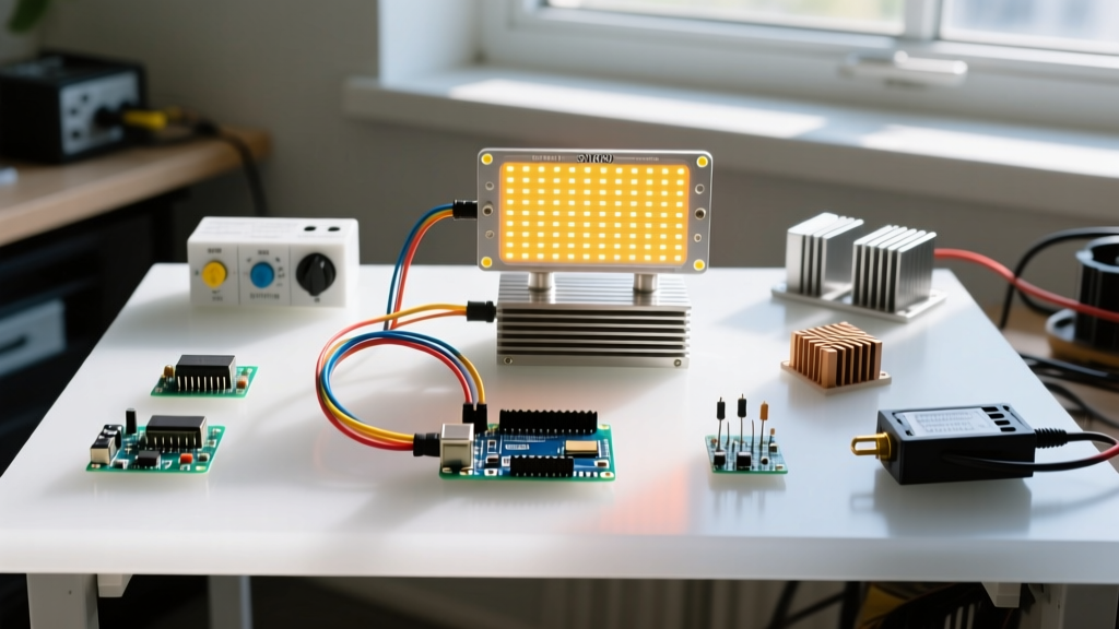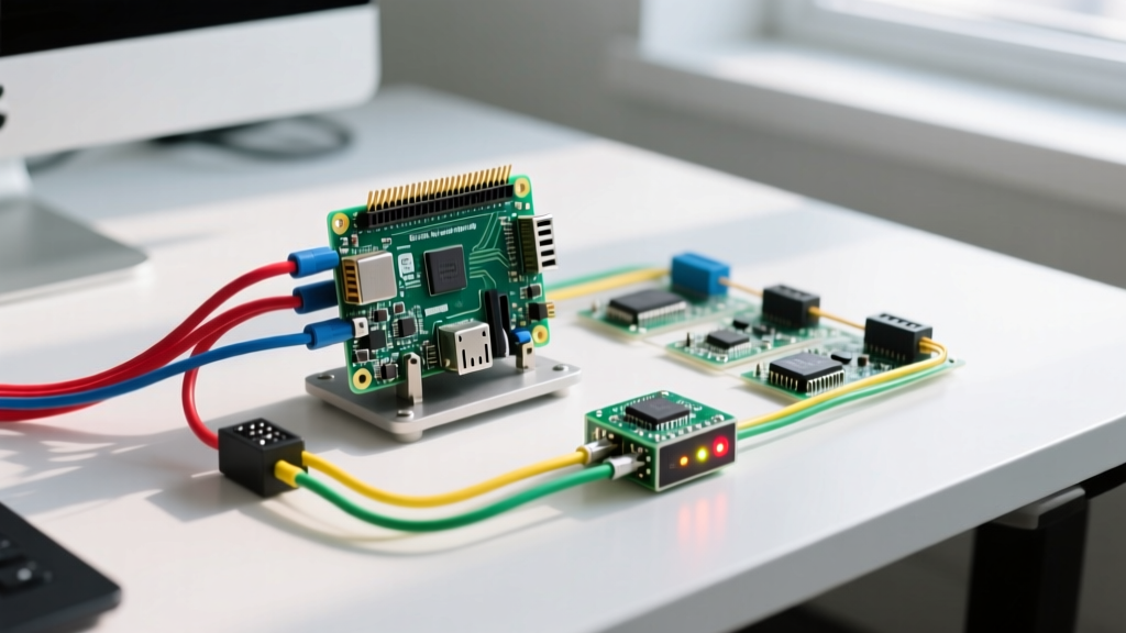

The Raspberry Pi handles digital input/output via its 40-pin header using 3.3V logic, but driving real-world loads requires bridging the gap between low-voltage logic and high-current actuators. For reliable input output raspberry pi projects, you must pair an opto-isolated relay module with a modern, event-driven library like gpiozero. This guide walks through building a robust physical control hub: reading a debounced momentary switch (input) to safely toggle a 5V relay (output) without frying your Pi's System-on-Chip.
Decision Tree: Which Board and Library Stack?
Before ordering parts, you need to lock in your hardware and software stack. The Raspberry Pi 5 introduced the RP1 southbridge chip, which changed how GPIO memory mapping works, breaking many legacy C/C++ and older Python libraries. For industrial-style GPIO automation in 2026, stability is paramount.
| Use Case | Recommended Board | Library | Verdict |
|---|---|---|---|
| High-speed bit-banging (WS2812 LEDs, raw RF) | Pi 4 Model B or Pi Pico | C/C++ (pigpio) | Specialized |
| Legacy codebase maintenance | Pi 4 Model B | RPi.GPIO (Python) | Deprecated |
| Standard relays, buttons, sensors, and IoT hubs | Pi 4 Model B (4GB) | gpiozero (Python) | DEFAULT PICK |
gpiozero library. It offers the best balance of 3.3V GPIO compatibility, massive community support, and native event-driven callbacks without the memory-mapping quirks of the Pi 5's RP1 chip.
Parts List & Pin Mapping Spec Sheet
Do not substitute the relay module. A bare 5V relay coil will dump inductive flyback voltage straight into your Pi's 3.3V rail when it de-energizes, instantly killing the SoC. You must use a module with an opto-isolator and a flyback diode.
Bill of Materials
- Compute: Raspberry Pi 4 Model B (4GB) + Official 27W USB-C Power Supply
- Storage: SanDisk 32GB Extreme microSD (A1 rated for OS longevity)
- Output Module: 5V 1-Channel Opto-isolated Relay Module (Songle SRD-05VDC-SL-C with PC817 optocoupler)
- Input Component: 12mm Momentary Pushbutton Switch (Normally Open)
- Passives: 10kΩ through-hole resistor (for external pull-down), 330Ω resistor (for optional status LED)
- Wiring: 22 AWG solid core hookup wire, half-size breadboard
Pin Mapping Table (BCM Numbering)
The gpiozero library defaults to Broadcom (BCM) pin numbering, not the physical pin numbers on the board. Always verify your physical layout against the BCM map.
| Component | BCM GPIO | Physical Pin | Direction | Notes |
|---|---|---|---|---|
| Pushbutton Switch | GPIO 17 | 11 | INPUT | Requires 10kΩ external pull-down to GND |
| Relay Module (IN) | GPIO 22 | 15 | OUTPUT | Active HIGH (triggers on 3.3V) |
| Status LED (Anode) | GPIO 23 | 16 | OUTPUT | Wire 330Ω resistor in series |
| Power (Relay VCC) | 5V | 2 or 4 | POWER | Do NOT use 3.3V for relay coil power |
| Ground (Common) | GND | 6, 9, 14, etc. | GROUND | Shared ground for Pi, relay, and breadboard |
Step-by-Step Wiring & Setup
Follow these steps in order. Always wire the ground and power rails first, then signal wires, to prevent floating logic states from triggering the relay erratically while you build.
- Establish Power Rails: Connect Physical Pin 2 (5V) to the breadboard's positive rail, and Physical Pin 6 (GND) to the negative rail.
- Wire the Relay Module: Connect the relay's VCC to the 5V rail. Connect the relay's GND to the negative rail. Connect the relay's 'IN' pin to GPIO 22 (Physical 15).
- Build the Input Circuit: Place the pushbutton across the breadboard's center trench. Connect one side of the button to the 3.3V rail (Physical Pin 1). Connect the other side to GPIO 17 (Physical 11).
- Add the Pull-Down Resistor: Insert the 10kΩ resistor between the GPIO 17 side of the button and the GND rail. This ensures the pin reads a solid LOW (0V) when the button is open, preventing phantom triggers from electromagnetic interference.
- Wire the Status LED: Connect the LED anode (long leg) to GPIO 23 (Physical 16) via the 330Ω resistor, and the cathode (short leg) to GND.
- Boot and Verify: Power up the Pi. Open a terminal and run
pinout(included in Raspberry Pi OS) to visually verify your BCM pin assignments against the physical board.
Complete Python Code for GPIO Input/Output
This script uses gpiozero, the officially recommended library by the Raspberry Pi Foundation. It utilizes hardware-level debouncing and event-driven callbacks, meaning it uses virtually zero CPU while waiting for an input state change.
from gpiozero import Button, LED, OutputDevice
from signal import pause
import logging

# --- PIN DEFINITIONS (BCM Numbering) ---
PIN_BUTTON = 17     # Physical Pin 11
PIN_RELAY = 22      # Physical Pin 15
PIN_STATUS_LED = 23 # Physical Pin 16

# Configure logging for production-level debugging
logging.basicConfig(
    level=logging.INFO,
    format='%(asctime)s - %(levelname)s - %(message)s'
)

def main():
    try:
        # Initialize components
        # pull_up=False means we are using an external pull-DOWN resistor to GND.
        # bounce_time=0.05 ignores mechanical contact bounce for 50ms.
        button = Button(PIN_BUTTON, pull_up=False, bounce_time=0.05)

        # OutputDevice is used for the relay since it's not strictly an 'LED'
        # active_high=True means the relay triggers when the pin goes to 3.3V
        relay = OutputDevice(PIN_RELAY, active_high=True, initial_value=False)
        status_led = LED(PIN_STATUS_LED, initial_value=False)

        def toggle_system():
            relay.toggle()
            status_led.toggle()
            state = 'ENGAGED' if relay.value else 'DISENGAGED'
            logging.info(f'Relay {state} via physical button press.')

        # Bind the event callback
        button.when_pressed = toggle_system

        logging.info('Input/Output hub active. Awaiting button press...')
        logging.info('Press Ctrl+C to safely exit.')

        # Keep the script running without consuming CPU cycles
        pause()

    except KeyboardInterrupt:
        logging.info('Shutdown sequence initiated by user.')
    except Exception as e:
        logging.error(f'Critical failure in GPIO loop: {e}')
    finally:
        # gpiozero handles cleanup on exit automatically, but explicit
        # closure ensures pins are released if the script is imported as a module.
        try:
            relay.close()
            status_led.close()
            button.close()
            logging.info('GPIO pins safely released.')
        except Exception:
            pass

if __name__ == '__main__':
    main()
Debugging: First Three Things to Check When It Fails
When your input output raspberry pi circuit misbehaves, do not immediately rewrite the code. 90% of GPIO failures are physical or OS-level configuration issues. Check these three items first:
- Power Supply Brownout: If the relay clicks but the Pi reboots or freezes, your power supply is sagging. A 5V relay coil draws ~70mA on top of the Pi's baseline. Use the official 27W USB-C supply and check for the lightning bolt icon on the display.
- Floating Inputs (Phantom Triggers): If the relay toggles randomly without you touching the button, your input pin is floating. Verify the 10kΩ pull-down resistor is securely connected to GND. Never rely solely on internal pull-ups/pull-downs for noisy environments.
- Pin Numbering Mismatch: If nothing happens, ensure your code uses BCM numbering (e.g., 17) and not physical board numbering (e.g., 11).
gpiozerostrictly expects BCM.
Exact Error Strings and Ranked Causes
If the script crashes immediately upon execution, match your terminal output to these exact error strings:
| Exact Error String | Ranked Causes & Fixes |
|---|---|
RuntimeError: Not running on a RPi! |
1. You are running the script inside a standard Docker container without passing the --privileged flag or mapping /dev/gpiomem.2. You are running the code on a non-Pi SBC (like an Orange Pi) where the gpiozero pin factory cannot detect the Broadcom SoC.
|
PermissionError: [Errno 13] Permission denied: '/sys/class/gpio/export' |
1. Your user is not in the gpio group. Fix: run sudo usermod -aG gpio $USER and reboot.2. You are using an outdated OS version lacking proper udev rules for /dev/gpiomem. Update via sudo apt update && sudo apt full-upgrade.
|
Extending and Simplifying the Build
Once the baseline hub is stable, you can scale the system up for home automation or scale it down for embedded deployment.
How to Extend (Add I2C Sensors)
To make this a true environmental controller, add a BME280 I2C sensor (approx. $6) to read temperature and humidity. Wire the BME280 VCC to 3.3V, GND to GND, SDA to GPIO 2 (Pin 3), and SCL to GPIO 3 (Pin 5). Install the Adafruit library via pip3 install adafruit-circuitpython-bme280. You can then modify the Python script to automatically trigger the relay if the temperature exceeds 28°C, turning on an exhaust fan.
How to Simplify (Headless Deployment)
If you are deploying this inside an electrical enclosure and don't need the status LED or console logging, strip the code down to the bare Button and OutputDevice classes. To ensure the script survives a reboot, create a systemd service file at /etc/systemd/system/relay-hub.service pointing to your Python script. This eliminates the need for cron @reboot hacks and provides automatic restart capabilities if the script encounters a fatal memory error.
For deeper hardware specifications and electrical tolerances, always consult the official Raspberry Pi hardware documentation before connecting inductive loads to the GPIO header.