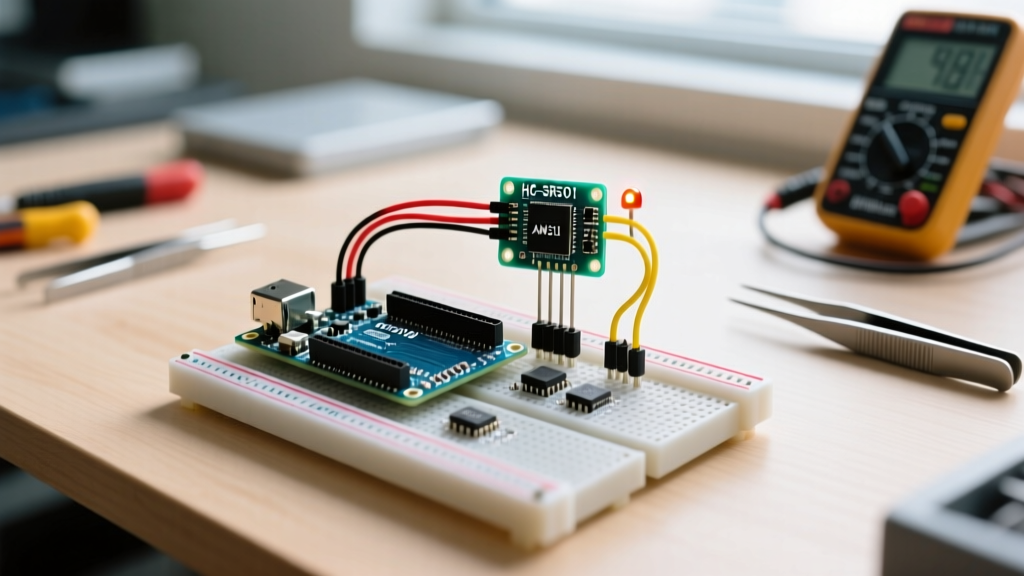
The original ESP32 changed the embedded landscape, but the ESP32-S3 fixes its most frustrating hardware bottlenecks. If you are planning new ESP32-S3 projects, the primary draw is the native USB OTG (On-The-Go) interface, which eliminates the need for external USB-to-UART bridge chips like the CP2102 or CH340. This means native USB Serial, USB HID (keyboards/mice), and direct USB mass storage capabilities straight from the silicon. Combined with vector instructions for AI acceleration and a dual-core Xtensa LX7 running at 240MHz, the S3 is a massive upgrade for edge sensor hubs.
In this guide, we are building a USB-Native Smart Sensor Hub. It reads environmental data over I2C and streams it directly to your PC via the native USB CDC serial port, using the onboard addressable RGB LED for real-time hardware status feedback. No external serial adapters required.
Project Spec Sheet & Parts List
| Parameter | Specification |
|---|---|
| Difficulty | Intermediate (I2C & Native USB config) |
| Build Time | 45 minutes |
| Target Board | ESP32-S3-DevKitC-1 (N8R2 variant) |
| Operating Voltage | 3.3V logic, 5V USB input |
Before you start wiring, verify your board variant. The code and pinouts below specifically target the ESP32-S3-DevKitC-1 (N8R2). This variant includes 8MB of Quad SPI flash and 2MB of Octal SPI PSRAM. If you have the N8 (no PSRAM) or a different dev board like the LilyGO T-Display S3, the GPIO mappings for the onboard RGB LED will differ.
Required Components
- Microcontroller: ESP32-S3-DevKitC-1 (N8R2) — ~$8.00
- Sensor: BME280 Breakout Board (I2C, 3.3V logic) — ~$6.00 (Avoid the cheaper BMP280 if you need humidity).
- Indicator: WS2812B 5V Through-hole LED (The DevKitC-1 has one on GPIO48, but we will wire an external one for breadboard visibility) — ~$0.20
- Resistor: 330Ω (for WS2812 data line protection)
- Misc: Half-size breadboard, 22 AWG solid jumper wires, USB-C data cable (crucial: must be data-capable, not charge-only).
Hardware Wiring & Pin Mapping
The ESP32-S3 has a highly flexible GPIO matrix, meaning you can route I2C to almost any pin. However, for this build, we are using GPIO38 and GPIO39 to keep the wiring clean on the DevKitC-1's left bank. Note that the S3's internal pull-ups are weak (typically 45kΩ); if your BME280 breakout lacks onboard 4.7kΩ pull-up resistors, I2C communication will fail at higher clock speeds.
| ESP32-S3 Pin | Component | Component Pin | Notes |
|---|---|---|---|
| 3V3 | BME280 | VIN / VCC | Do not use 5V; BME280 is strictly 3.3V. |
| GND | BME280 | GND | Common ground required. |
| GPIO 38 | BME280 | SDA | I2C Data line. |
| GPIO 39 | BME280 | SCL | I2C Clock line. |
| 5V | WS2812B | VCC (+5V) | WS2812 requires 5V for full brightness. |
| GND | WS2812B | GND | Common ground. |
| GPIO 48 | WS2812B | DIN (via 330Ω) | Data line. 330Ω resistor prevents ringing. |
0x76. If left floating, the address defaults to 0x77 and the code below will fail to initialize.
Complete Firmware: USB Serial & I2C Sensor Code
This firmware uses the Adafruit BME280 and NeoPixel libraries. It includes explicit error handling: if the I2C sensor fails to initialize, the code will not silently hang; it will turn the LED red and halt, preventing you from chasing ghost bugs in the serial monitor.
Crucial Arduino IDE Setting: Before uploading, go to Tools -> USB CDC On Boot and select Enabled. If you leave this disabled, the Serial object will route to the hardware UART pins instead of the native USB-C port, and you will see no output on your PC.
#include <Wire.h>
#include <Adafruit_Sensor.h>
#include <Adafruit_BME280.h>
#include <Adafruit_NeoPixel.h>

// --- Pin Definitions for ESP32-S3-DevKitC-1 ---
#define PIN_I2C_SDA   38
#define PIN_I2C_SCL   39
#define PIN_NEOPIXEL  48
#define NEOPIXEL_COUNT 1
#define SEALEVELPRESSURE_HPA (1013.25)

// Initialize objects
Adafruit_BME280 bme;
Adafruit_NeoPixel pixel(NEOPIXEL_COUNT, PIN_NEOPIXEL, NEO_GRB + NEO_KHZ800);

void setup() {
  // Initialize Native USB CDC Serial
  Serial.begin(115200);

  // Wait up to 3 seconds for USB serial connection to establish
  uint32_t start_time = millis();
  while (!Serial && (millis() - start_time) < 3000) {
    delay(10);
  }

  // Initialize NeoPixel
  pixel.begin();
  pixel.setBrightness(20); // Keep brightness low to protect the S3's 3.3V LDO
  pixel.clear();
  pixel.show();

  // Initialize I2C with explicit S3 pins
  Wire.begin(PIN_I2C_SDA, PIN_I2C_SCL);
  Wire.setClock(400000); // 400kHz Fast Mode

  Serial.println("Initializing BME280 Sensor...");

  // Error Handling: Check for sensor presence
  if (!bme.begin(0x76, &Wire)) {
    Serial.println("[FATAL] Could not find a valid BME280 sensor at 0x76!");
    Serial.println("Check wiring, I2C pull-ups, and SDO pin state.");

    // Visual Error Indicator: Solid Red
    pixel.setPixelColor(0, pixel.Color(255, 0, 0));
    pixel.show();

    // Halt execution to prevent garbage data loops
    while (1) {
      delay(1000);
    }
  }

  Serial.println("BME280 initialized successfully.");
  // Visual Success Indicator: Solid Green
  pixel.setPixelColor(0, pixel.Color(0, 255, 0));
  pixel.show();
  delay(1000);
}

void loop() {
  // Read sensor data
  float temperature = bme.readTemperature();
  float humidity = bme.readHumidity();
  float pressure = bme.readPressure() / 100.0F;
  float altitude = bme.readAltitude(SEALEVELPRESSURE_HPA);

  // Format and print via Native USB Serial
  Serial.printf("Temp: %.2f C | Hum: %.1f %% | Press: %.1f hPa | Alt: %.1f m\n",
                temperature, humidity, pressure, altitude);

  // Dynamic LED feedback: Blue pulse based on humidity
  int blue_val = map((int)humidity, 0, 100, 10, 255);
  pixel.setPixelColor(0, pixel.Color(0, 0, blue_val));
  pixel.show();

  delay(2000); // 2-second polling interval
}
Debugging the ESP32-S3: Boot Failures and USB Dropouts
The most common roadblock in ESP32-S3 projects is the upload process. Because the S3 uses native USB instead of a dedicated hardware UART bridge, the boot sequence behaves differently than the original ESP32. If your upload fails, you will likely see this exact error string in the Arduino IDE output:
A fatal error occurred: Failed to connect to ESP32-S3: No serial data received.
- The Cable: 90% of 'dead' S3 boards are actually charge-only USB-C cables. Verify your cable supports data transfer by plugging it into a phone and checking if the PC recognizes it.
- The Boot State: The S3 does not always auto-reset into download mode via the USB D- line like older chips. You must manually force it.
- The IDE Port Selection: When the S3 enters download mode, it sometimes changes its COM port identifier (e.g., from 'USB JTAG/serial debug unit' to 'USB Serial Device'). You may need to re-select the port in the IDE.
Ranked Causes and Fixes for Connection Failures
1. Board is stuck in standard boot mode (Most Likely)
Fix: Press and hold the BOOT button (GPIO0) on the DevKitC-1. While holding it, tap the RST button, then release the BOOT button. Click 'Upload' in the IDE immediately after.
2. USB CDC conflicting with Hardware UART
Fix: If your code previously used Serial.begin() but 'USB CDC On Boot' was disabled, the S3 might be routing serial to UART0, confusing the native USB bootloader. Ensure 'USB CDC On Boot' is set to Enabled and 'USB Mode' is set to Hardware CDC and JTAG in the Tools menu.
3. Insufficient USB Current Limiting
Fix: If you have external 5V peripherals (like a long strip of WS2812s) drawing power from the DevKit's 5V pin, the PC's USB port might brownout and drop the data connection. Power high-draw peripherals from a dedicated 5V bench supply, tying the grounds together.
For deeper architectural details on the S3's USB subsystem, refer to the Espressif ESP32-S3 Technical Reference Manual, specifically Chapter 33 (USB Serial/JTAG Controller).
Extending and Simplifying the Build
One of the best aspects of the ESP32-S3 is how easily you can scale the hardware up or down based on your project constraints.
How to Simplify (The 'Bare Minimum' Test)
If you are waiting on parts or just want to verify the native USB serial pipeline, strip out the BME280 and the external NeoPixel. The ESP32-S3 has an internal temperature sensor located inside the silicon die. While it reads about 5-10°C higher than ambient due to chip self-heating, it is perfect for a basic sanity check. Replace the I2C initialization with temperatureRead() (available in the ESP32 Arduino core) and print the result to the serial monitor. This requires zero external wiring.
How to Extend (Advanced S3 Features)
- Add I2S Audio: The S3's vector instructions make it ideal for audio processing. Wire an INMP441 MEMS microphone to the I2S pins and use the 2MB PSRAM to buffer audio chunks before sending them over WiFi.
- Implement ESP-NOW: Instead of streaming data to a PC via USB, configure the S3 to broadcast the BME280 telemetry via ESP-NOW to a receiver node. ESP-NOW bypasses the WiFi router, offering sub-10ms latency and drastically lower power consumption.
- USB HID Keyboard: Because the S3 has native USB OTG, you can use the
USB.handUSBHIDKeyboard.hlibraries to turn your sensor hub into a macro keypad that types out the temperature readings directly into any open text field on a host PC.
ESP32-S3 Projects FAQ
Why do my ESP32-S3 projects fail to upload over native USB?
Unlike the original ESP32, which used an external chip (like the CP2102) to automatically toggle the EN and GPIO0 pins via the DTR/RTS serial lines, the ESP32-S3's native USB port does not always reliably trigger the auto-reset circuit during the upload handshake. If auto-reset fails, you must manually hold the BOOT button, tap RESET, and then release BOOT to force the chip into the serial bootloader.
Can I use standard ESP32 code for ESP32-S3 projects without changes?
Mostly, but not entirely. Standard WiFi, BLE, and GPIO code will compile fine. However, you will run into issues if your code relies on the original ESP32's specific ADC pin mappings (the S3 has different ADC1/ADC2 assignments), or if it uses the capacitive touch pins, which are routed differently on the S3. Furthermore, any code relying on hardware UART serial output will fail to show up on your PC's USB port unless you explicitly enable 'USB CDC On Boot' in the IDE and map your hardware UARTs to external pins.
How do I enable the native USB CDC serial port in the Arduino IDE for ESP32-S3 projects?
In Arduino IDE 2.x, select your ESP32-S3 board, then navigate to the Tools menu. Set USB Mode to 'Hardware CDC and JTAG', set USB CDC On Boot to 'Enabled', and set Upload Mode to 'UART0 / Hardware CDC'. This configuration routes the Serial object to the USB-C port while keeping the hardware JTAG debugger active for advanced step-through debugging.
What is the maximum current draw for the ESP32-S3-DevKitC-1 5V pin?
The 5V pin on the DevKitC-1 is directly tied to the USB-C input, minus the protection diode and polyfuse. Most PC USB 3.0 ports can supply 900mA, and USB 2.0 supplies 500mA. However, the onboard polyfuse typically trips around 700mA to 1A. If your external 5V sensors or LED strips draw more than 500mA continuously, you should bypass the board's 5V rail and power the peripherals directly from a dedicated 5V power supply, ensuring you connect the grounds together. For more on power limits, consult the Espressif Arduino Core documentation.