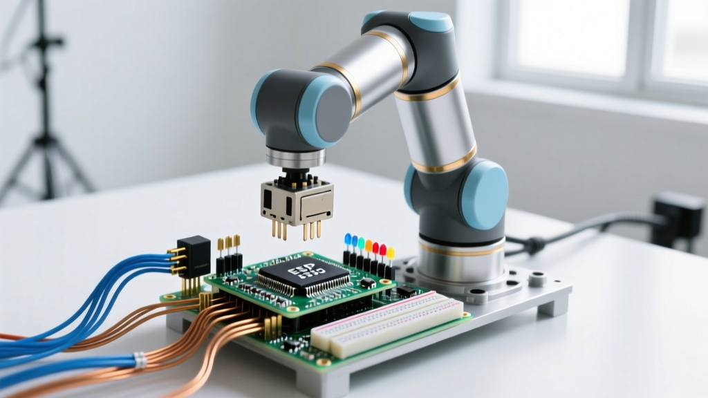
Open source robots are robotic platforms where the hardware schematics, mechanical CAD files, and firmware source code are publicly licensed for anyone to study, modify, and manufacture. In a real embedded circuit, this transparency changes everything: instead of being locked out of a proprietary motor controller's black-box SDK, you get direct access to the MCU's PWM registers, encoder interrupts, and I2C buses to write custom sensor fusion algorithms. Builders commonly confuse 'open source software' (like running open-source ROS 2 nodes on a closed-hardware commercial robot) with true 'open source hardware' (where the PCB Gerbers, bill of materials, and 3D-printable chassis files are fully published under licenses like the CERN Open Hardware Licence).
When you design or modify an open source robot, you are responsible for the entire stack—from the lithium cell discharge curves to the ROS 2 joint state publishers. Below is a breakdown of the standard microcontroller architectures used in modern open-hardware robotics.
| Architecture Tier | Typical MCU/SBC | ROS 2 Integration Method | Max I2C/SPI Bus Speed | Typical BOM Cost (2026) |
|---|---|---|---|---|
| Low-Level Actuator Node | ESP32-S3 (Dual-core 240MHz) | Micro-ROS via UART/WiFi | 1MHz (I2C) / 80MHz (SPI) | $12 - $18 |
| Mid-Tier Vision Rover | Raspberry Pi 5 (8GB) | Native ROS 2 Jazzy | N/A (Uses USB/I2C Mux) | $85 - $110 |
| High-Performance Quadruped | Jetson Orin Nano + STM32H7 | Native + Custom CAN-FD Bridge | 400kHz (I2C) / 50MHz (SPI) | $250 - $350 |
| Swarm Micro-Rover | ATmega328P + ESP8266 | Custom MQTT to ROS Bridge | 400kHz (I2C) / N/A | $8 - $12 |
Sizing the Sensor Bus for Open Hardware
When you download the open-source PCB files for a rover and decide to add your own sensor array, you immediately run into bus capacitance limits. Let's look at a concrete numeric example: calculating the I2C pull-up resistors for an ESP32-S3 driving a BNO085 IMU and two VL53L1X Time-of-Flight (ToF) sensors on a custom open-source PCB.
The I2C specification limits total bus capacitance (Cb) to 400 pF for standard and fast modes. Let's calculate the required pull-up resistor (Rp) for a 3.3V logic system running at 400kHz (Fast Mode).
- Trace capacitance: ~2 pF per inch. Assuming 10 inches of traces = 20 pF.
- BNO085 pin capacitance: ~10 pF.
- Two VL53L1X sensors: ~10 pF each = 20 pF.
- ESP32-S3 pin capacitance: ~10 pF.
- Total Cb: 20 + 10 + 20 + 10 = 60 pF.
First, we find the minimum pull-up resistance based on the maximum allowable sink current (Iol = 3mA) and maximum low-level output voltage (Vol = 0.4V):
Rp(min) = (Vcc - Vol) / Iol = (3.3 - 0.4) / 0.003 = 966 Ω
Next, we calculate the maximum pull-up resistance to ensure the rise time (tr) stays under the 300ns limit for Fast Mode, using the standard RC approximation Rp(max) = tr / (0.8473 × Cb):
Rp(max) = 300ns / (0.8473 × 60pF) ≈ 5,901 Ω
Where You Meet Open Source Robots in Practice
You will rarely see true open-hardware robots in consumer retail; they thrive in environments where customization and repairability are paramount.
- University Research Labs: Swarm robotics and SLAM (Simultaneous Localization and Mapping) research rely heavily on open hardware. When a lab needs to test a novel LiDAR placement algorithm, they can physically alter the 3D-printed chassis and recompile the ROS 2 Jazzy navigation stack without waiting for a vendor firmware update.
- Precision Agriculture: Open-source autonomous weeders use Raspberry Pi compute modules paired with OAK-D spatial cameras. Farmers and ag-tech startups modify the mechanical actuator files to adjust the hoe width for different crop row spacing, a flexibility impossible with closed-source commercial equivalents.
- Hobbyist Inspection Rovers: Makers building pipe-inspection or cave-mapping rovers use open-source motor controller boards (like the ODrive or VESC) because they can tune the field-oriented control (FOC) parameters to handle the high-stall currents required when a rover gets wedged in debris.
Firmware Architecture: Bridging the MCU and ROS 2
The most critical decision when building an open source robot is how your low-level microcontroller talks to your high-level compute board. The industry standard has shifted heavily toward Micro-ROS, which allows RTOS-based microcontrollers (like the ESP32 running FreeRTOS) to act as native ROS 2 nodes.
In a typical differential-drive rover, the Raspberry Pi runs the heavy SLAM and Nav2 stacks, while the ESP32-S3 handles the real-time odometry and motor PID loops. The ESP32 publishes sensor_msgs/JointState and subscribes to geometry_msgs/Twist via Micro-ROS.
Common Failure Mode: Wi-Fi latency and packet drops. If you use the default Micro-ROS Wi-Fi transport (UDP over XRCE-DDS), a momentary drop in your 2.4GHz Wi-Fi network will cause the ESP32 to lose connection to the ROS 2 agent. The ESP32's watchdog will trigger, resetting the board and leaving your robot rolling blindly into a wall.
The Fix: For the base controller link, bypass Wi-Fi entirely. Wire the ESP32's UART1 (GPIO 16/17) directly to the Raspberry Pi's hardware serial pins or a USB-to-Serial adapter. Configure the Micro-ROS agent to use serial transport (ros2 run micro_ros_agent micro_ros_agent serial --dev /dev/ttyUSB0). This guarantees deterministic latency for your ros2_control hardware interface, ensuring your PID loops receive velocity commands at a rock-solid 50Hz.
FAQ: Debugging Open Source Robot Builds
Why does my I2C bus hang the moment the drive motors spin up?
This is almost always Electromagnetic Interference (EMI). Brushed DC motors generate massive voltage spikes and high-frequency noise that couples into your unshielded SDA and SCL lines, causing the I2C state machine in your MCU to lock up. Fix: Use twisted-pair wiring for your I2C bus, add 100nF ceramic decoupling capacitors directly at the VCC/GND pins of every sensor, and implement a star-grounding topology so the high-current motor return path does not share a ground trace with your logic sensors.
My Micro-ROS agent crashes when I reboot the ESP32. How do I make it auto-reconnect?
By default, the Micro-ROS agent on the host PC doesn't gracefully handle the sudden disappearance and reappearance of the serial client. If you are running the agent on a Raspberry Pi, do not run it manually in a terminal. Instead, write a systemd service file for the agent and include the Restart=always and RestartSec=2 directives. This ensures the agent automatically respawns and re-establishes the XRCE-DDS session the moment the ESP32 finishes its boot sequence.
Can I power the ESP32 and the sensors directly from the motor driver's 5V BEC?
You can, but you shouldn't. Cheap Battery Eliminator Circuits (BECs) on motor drivers often have poor transient response. When your motors stall and draw 20A, the BEC voltage can sag below 4.5V, causing the ESP32's internal brownout detector to trigger a silent reset. Use a dedicated, high-quality buck converter (like a Pololu D24V50F5) wired directly to the main battery terminals to supply your logic 5V rail, keeping it completely isolated from the motor power spikes.