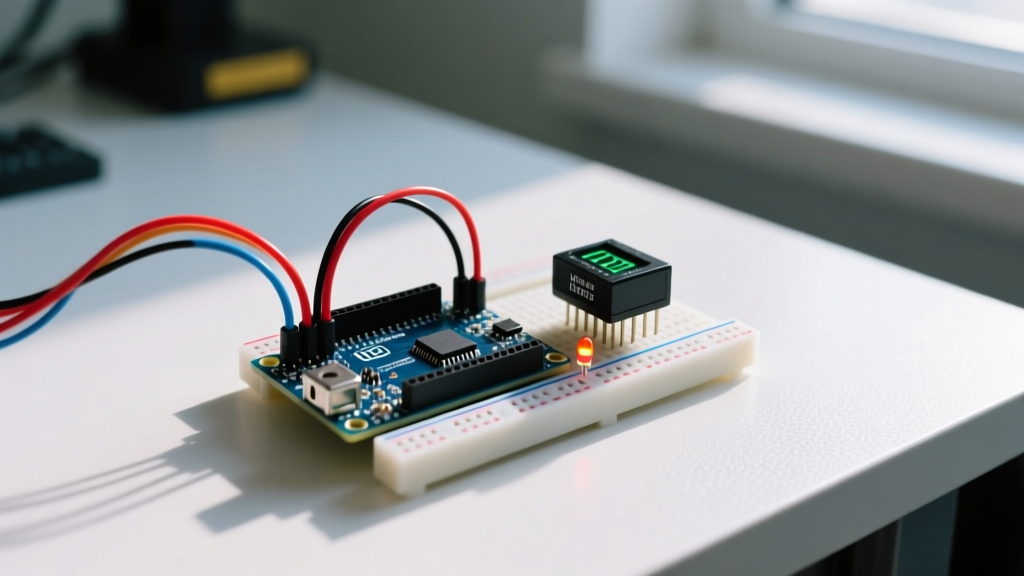
A robotic manipulator is a programmable, multi-axis mechanical arm that uses microcontroller-driven actuators to move an end-effector through 3D space to interact with objects. When you transition from building simple mobile rovers to manipulator robotics, your circuit design fundamentally changes: you shift from continuous-rotation H-bridge motor control to multi-channel, synchronized pulse-width modulation (PWM) or serial bus communication, requiring strict hardware-timer reliance and massive instantaneous current headroom. Beginners commonly confuse articulated manipulators with CNC gantries (which use rigid Cartesian rails and stepper motors) or mobile robots (which prioritize navigation over spatial interaction); manipulators specifically deal with rotary joints, angular kinematics, and reaching around obstacles in a shared workspace.
The Physics of a Manipulator: Static Torque and Sizing
The most common failure point in DIY manipulator robotics is undersizing the base and shoulder servos. Unlike a wheeled robot where friction and momentum carry the load, a manipulator arm must fight gravity at full extension. This requires calculating the static holding torque at each joint.
Assume a 2-link planar arm. Link 1 is 200mm, Link 2 is 150mm. Your target payload is 500g (0.5 kg). The worst-case scenario for the base (shoulder) joint is when the arm is fully extended horizontally.
- Total Reach: 0.20m + 0.15m = 0.35m
- Payload Force: 0.5 kg × 9.81 m/s² = 4.905 N
- Payload Torque: 4.905 N × 0.35m = 1.716 Nm (approx. 17.5 kg-cm)
But we must also account for the arm's own weight. If the aluminum links and servos weigh 400g (distributed, so center of mass is roughly at 0.175m), that adds another ~7 kg-cm. Your total required static holding torque is ~24.5 kg-cm. Applying a standard 1.5x safety factor for dynamic acceleration, you need a base servo rated for at least 36.7 kg-cm. A standard MG996R (13 kg-cm) will instantly stall and strip its gears here.
Where You Meet Manipulator Robotics in Practice
In the maker and embedded space, you will typically encounter manipulator robotics in three applications: automated pick-and-place sorting (often using computer vision via an ESP32-CAM or Raspberry Pi), camera gimbals for stabilization, and automated soldering or glue-dispensing rigs.
In a real circuit installation, adding a manipulator changes your power topology entirely. A 6-Degree-of-Freedom (6-DOF) arm using six standard 5V servos can draw upwards of 15A during a simultaneous stall or rapid direction reversal. If you attempt to power this from the onboard 5V regulator of an Arduino Mega or the USB VBUS pin of an ESP32, you will trigger an immediate brownout reset, crashing your microcontroller and potentially corrupting its flash memory. You must design a split power rail: logic power (3.3V/5V at <500mA) for the MCU, and a high-current actuator power rail (5V-8.4V at 20A+) for the servos, joined only at a single common ground point to prevent ground loops.
Hardware Decision Tree: Sizing Your MCU and Actuators
Choosing the right combination of microcontroller, motor driver, and actuator depends on your Degrees of Freedom (DOF) and payload requirements. Use this decision matrix to select your hardware stack.
| Application Profile | MCU Choice | Driver / Interface | Actuator Pick |
|---|---|---|---|
| Lightweight (Under 3 DOF, <500g payload) | Arduino Nano / ESP32-C3 | Direct MCU Hardware PWM Pins | TowerPro MG90S (Metal Gear, 2.2 kg-cm) |
| Medium (4-6 DOF, 1-2kg payload) | ESP32 DevKit V1 (Dual Core) | PCA9685 I2C 16-Channel PWM Driver | DSServo DS3218 (20 kg-cm, 270°) |
| Heavy / High Precision (6+ DOF, >3kg payload) | Raspberry Pi 4 / ESP32-S3 | Half-Duplex UART Serial Bus | LewanSoul LX-22A or Feetech SCS15 (Serial Bus, 17+ kg-cm) |
| Default 6-DOF Pick (Best Balance of Cost/Performance) | ESP32 DevKit V1 | Adafruit PCA9685 Breakout | DSServo DS3225 (25 kg-cm) |
Concrete Recommendation: For a standard 6-DOF desktop arm, buy the ESP32 DevKit V1 paired with a PCA9685 I2C driver and six DS3225 25kg-cm servos. The ESP32 handles the inverse kinematics math on its floating-point unit, while the PCA9685 offloads the PWM generation, guaranteeing zero jitter.
Control Architecture: Inverse Kinematics and Timer Jitter
To move a manipulator's end-effector to a specific X, Y, Z coordinate, the microcontroller must solve Inverse Kinematics (IK). This involves trigonometric calculations to determine the exact angle required at each rotary joint. For a 6-DOF arm, this requires heavy matrix math. While an ATmega328P (Arduino Uno) struggles with floating-point IK calculations in real-time, the ESP32's dual-core 240MHz Tensilica processors handle it effortlessly. For advanced trajectory planning and ROS2 integration, the ROS2 Humble documentation provides standard MoveIt frameworks that run on a Raspberry Pi, sending joint-angle commands down to the ESP32 via serial.
A critical embedded concept here is PWM jitter. Standard hobby servos expect a 50Hz PWM signal with a pulse width between 500µs and 2500µs. If your microcontroller uses software interrupts to generate this signal (like the default servo.write() on some generic Arduino cores), background tasks like WiFi interrupts on an ESP32 will delay the pulse edges. A jitter of just 10µs translates to physical vibration and mechanical wear in the arm. Always use hardware timers or an external I2C PWM driver like the Adafruit PCA9685, which generates the pulses independently of the MCU's main loop.
Power Delivery: Preventing the Brownout Reset
The most frequent troubleshooting ticket for DIY manipulator builds is the "random MCU reset during fast movements" error. This is almost always caused by voltage sag on the 5V rail. When a high-torque servo like the DS3225 starts moving under load, it can draw 2.5A to 3A momentarily. Multiply that by three servos moving simultaneously, and your power supply must deliver 9A+ without the voltage dropping below the MCU's brownout threshold (typically 4.2V for 5V logic systems).
Frequently Asked Questions
Can I use stepper motors instead of servos for a manipulator?
Yes, but it changes the architecture entirely. Steppers require homing switches (limit switches) on every axis because they operate in open-loop and don't know their absolute position on startup. Servos use internal potentiometers or magnetic encoders for absolute closed-loop positioning, making them much easier to wire and initialize for hobbyist manipulators.
Why do serial bus servos (like LewanSoul/Feetech) use half-duplex UART?
Half-duplex UART allows up to 253 servos to be daisy-chained on a single 3-wire cable (VCC, GND, Signal) using just one MCU TX/RX pin pair. The MCU sends a command packet, and the specific servo ID responds on the same wire. This drastically reduces the wiring harness complexity in a 6-DOF arm compared to running 12 individual PWM wires through the shoulder joint.