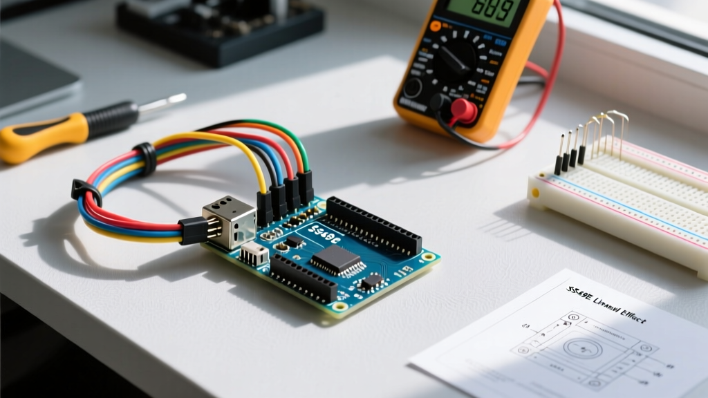

To measure magnetic field strength or proximity with a microcontroller, use a linear hall effect sensor with Arduino by wiring the VCC to 5V, GND to ground, and the analog output pin to an ADC channel (like A0). The Honeywell SS49E is the benchmark linear sensor for this, providing a ratiometric voltage output that scales from 1.5V to 4.5V across a ±100 mT (milliTesla) magnetic range. Unlike digital switch sensors that only snap HIGH or LOW, a linear sensor gives you continuous positional data, making it ideal for DIY throttle controls, liquid level floats, and non-contact potentiometers.
Linear vs. Switch: Choosing the Right Hall Sensor
Before soldering, you must select the correct sensor topology. Hobbyist bins are full of A3144 digital switches mistakenly bought by makers who actually needed analog position tracking. Here is how the three most common 5V-tolerant Hall ICs compare on the bench.
| Part Number | Topology | Output Type | Sensitivity | Quiescent (Null) Voltage | Typical Price (2026) |
|---|---|---|---|---|---|
| SS49E (Honeywell) | Linear | Analog (Ratiometric) | 1.4 mV/mT (typ) | VCC / 2 (approx 2.5V) | $1.20 - $1.80 |
| A3144 (Allegro) | Digital Switch | Open-Drain (Needs Pull-up) | N/A (Bop: 3.5 mT) | 0V or 5V (Digital) | $0.15 - $0.30 |
| DRV5055 (TI) | Linear | Analog (Ratiometric) | Up to 100 mV/mT | VCC / 2 | $0.80 - $1.10 |
| MLX90393 (Melexis) | 3-Axis Linear | I2C / SPI Digital | Configurable via I2C | N/A (Digital Data) | $3.50 - $4.50 |
Parts List and Pin Mapping
This build targets the Arduino Nano V3 (ATmega328P, 5V logic). The Nano is preferred over the Uno R3 for embedded sensor nodes due to its breadboard-friendly footprint, but the code and wiring map 1:1 to the Uno R3 or Mega 2560.
Bill of Materials
- Microcontroller: Arduino Nano V3 (ATmega328P) with CH340 or FT232RL USB-to-Serial chip.
- Sensor: SS49E Linear Hall Effect Sensor (TO-92 package).
- Magnet: N52 Neodymium cylinder (10mm diameter x 5mm thickness). Note: N52 grade provides ~20% more flux density at the sensor face than cheaper N42 grades.
- Passives: 100nF (0.1µF) ceramic capacitor for VCC decoupling; 10kΩ trimpot (optional, for hardware offset tuning).
- Wire: 22 AWG solid core hookup wire.
Pin Mapping Table
| SS49E Pin (TO-92) | Function | Arduino Nano V3 Pin | Notes |
|---|---|---|---|
| 1 (Left, flat side facing you) | VCC | 5V | Do not exceed 6.5V absolute max. |
| 2 (Middle) | GND | GND | Keep ground return path short to avoid noise. |
| 3 (Right) | VOUT | A0 | Analog input. 10-bit ADC resolution. |
Wiring and Calibration Steps
- De-energize the board: Unplug the USB cable from the Arduino Nano before inserting components into the breadboard to prevent accidental shorting of the 5V rail to the ADC pin.
- Seat the Sensor: Insert the SS49E into the breadboard. The flat face with the part number printed on it is the active sensing area. Ensure the pins are not bent and are in separate rows.
- Power and Ground: Wire Pin 1 to the Nano's 5V rail and Pin 2 to the GND rail.
- Decouple the VCC: Place the 100nF ceramic capacitor directly across the VCC and GND rails as close to the sensor's pins as physically possible. This shunts high-frequency switching noise from the Nano's voltage regulator away from the sensor's internal amplifier.
- Route the Signal: Connect Pin 3 (VOUT) to the Nano's A0 pin using a short jumper wire (under 3 inches to minimize capacitive coupling to digital traces).
- Verify with a Multimeter: Power the Nano via USB. Set your multimeter to DC Volts. Probe the A0 pin. With no magnet present, you should read between 2.45V and 2.55V (the quiescent null voltage). If you read 0V or 5V, your wiring is reversed or the sensor is dead.
Complete Arduino Code for Magnetic Field Mapping
The following C++ code targets the Arduino Nano V3. It reads the 10-bit ADC, applies a 16-sample moving average filter to eliminate 60Hz mains hum and breadboard noise, and calculates the estimated magnetic flux density in milliTesla (mT). It includes bounds checking to handle disconnected wires or saturated ADC states.
// Target Board: Arduino Nano V3 (ATmega328P, 5V/16MHz)
// Sensor: SS49E Linear Hall Effect Sensor

#define SENSOR_PIN A0
#define SAMPLE_SIZE 16
#define VCC_VOLTAGE 5.0       // Nominal USB VCC
#define ADC_RESOLUTION 1024.0 // 10-bit ADC
#define SENSITIVITY 1.4       // SS49E typical sensitivity in mV/mT

// Calibration offsets (measure these with no magnet present)
#define NULL_VOLTAGE 2.50     // Quiescent voltage in Volts

int readingBuffer[SAMPLE_SIZE];
int bufferIndex = 0;
long totalSum = 0;

void setup() {
  Serial.begin(115200);

  // Initialize ADC pin
  pinMode(SENSOR_PIN, INPUT);

  // Pre-fill the moving average buffer to prevent startup spikes
  int initialRead = analogRead(SENSOR_PIN);
  for (int i = 0; i < SAMPLE_SIZE; i++) {
    readingBuffer[i] = initialRead;
    totalSum += initialRead;
  }

  Serial.println("SS49E Hall Sensor Initialized. Calibrating null field...");
  delay(500);
}

void loop() {
  // 1. Read ADC and handle hardware errors
  int rawADC = analogRead(SENSOR_PIN);

  // Error handling: Check for floating pin or shorted rail
  if (rawADC <= 5 || rawADC >= 1018) {
    Serial.println("ERROR: Sensor disconnected, floating, or rail shorted. Check wiring.");
    delay(1000);
    return;
  }

  // 2. Update Moving Average Filter
  totalSum = totalSum - readingBuffer[bufferIndex];
  readingBuffer[bufferIndex] = rawADC;
  totalSum = totalSum + rawADC;
  bufferIndex = (bufferIndex + 1) % SAMPLE_SIZE;

  float avgADC = (float)totalSum / SAMPLE_SIZE;

  // 3. Convert ADC to Voltage
  float voltage = (avgADC / ADC_RESOLUTION) * VCC_VOLTAGE;

  // 4. Calculate Magnetic Field (mT)
  // Formula: B (mT) = (Vout - Vnull) / Sensitivity
  // Sensitivity is in mV/mT, so we multiply voltage delta by 1000
  float deltaV_mV = (voltage - NULL_VOLTAGE) * 1000.0;
  float magneticField_mT = deltaV_mV / SENSITIVITY;

  // 5. Output for Serial Plotter
  Serial.print("Raw:");
  Serial.print(rawADC);
  Serial.print("\tVoltage:");
  Serial.print(voltage, 3);
  Serial.print("\tField_mT:");
  Serial.println(magneticField_mT, 2);

  delay(50); // 20Hz sample rate
}
Debugging: First Three Things to Check When It Fails
Hall sensors are notoriously unforgiving of poor grounding and pin misassignments. If your build fails, follow this ranked decision path.
1. The Upload Error: avrdude: stk500_getsync() attempt 1 of 10: not in sync: resp=0x00
Cause: You accidentally wired the sensor's VOUT to Pin 0 (RX) or Pin 1 (TX) on the Nano instead of A0. The sensor's output voltage is interfering with the USB-to-Serial UART communication during the bootloader handshake.
Fix: Move the signal wire to A0. Never use digital pins 0 or 1 for analog sensors on ATmega328P boards.
2. The Runtime Error: Erratic ADC Jumps (e.g., 512, 1023, 0, 45)
Cause: A floating ground or missing decoupling capacitor. The Nano's onboard 5V regulator has high ripple; without the 100nF capacitor, the sensor's internal op-amp oscillates, and the breadboard's parasitic capacitance couples digital noise into the high-impedance ADC pin.
Fix: Verify the GND pin is tied to the Nano's GND (not a disconnected power rail). Solder or firmly seat the 100nF capacitor directly across the sensor's VCC and GND legs.
3. The Logic Error: Output Voltage Stuck at 2.5V Regardless of Magnet
Cause: You are using the wrong magnet pole, the magnet is too weak (e.g., a ceramic fridge magnet instead of Neodymium), or you are testing with a digital switch sensor (A3144) instead of the linear SS49E. The A3144 requires a specific South pole facing the flat branded side to trigger.
Fix: Verify the part number printed on the flat face. If it is an SS49E, flip the N52 magnet over. The SS49E responds to both poles (pushing voltage above 2.5V for South, below 2.5V for North), but the field must be perpendicular to the flat face, not parallel to the edge.
Extending and Simplifying the Build
Depending on your end application, you can scale this circuit up for industrial-style telemetry or strip it down for basic limit switching.
How to Simplify (Limit Switching)
If you only need to know if a magnet is present (e.g., a door alarm or RPM counter), discard the SS49E and use the A3144 digital switch. Wire its VOUT to a digital pin (e.g., D2) with a 10kΩ pull-up resistor to 5V. Use the attachInterrupt() function in your Arduino code to count pulses. This eliminates ADC noise, removes the need for moving average filters, and drops the sensor cost to under $0.20.
How to Extend (RPM and Angular Position)
To build a non-contact tachometer, mount four N52 magnets (alternating North/South poles) at 90-degree intervals on a rotating shaft. Point the SS49E at the passing magnets. By measuring the time delta (micros()) between the peak voltage crossings (when magneticField_mT crosses 0), you can calculate RPM with high resolution. For absolute angular position (like a steering angle sensor), pair the SS49E with a diametrically magnetized cylinder magnet and use the Arduino ADC to map the sine wave output directly to a 0-360 degree lookup table.
For further reading on magnetic flux densities and sensor selection, refer to Honeywell's SS49E datasheet and application notes, which detail the thermal drift characteristics you must account for if your project operates in unconditioned outdoor environments.


