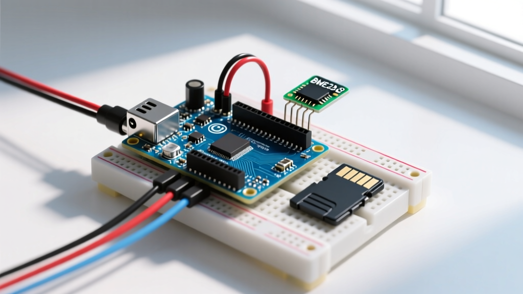
To connect an LCD display via I2C to a Raspberry Pi, use a 16x2 or 20x4 HD44780-compatible LCD equipped with a PCF8574 I2C backpack. Wire VCC to the Pi’s 5V (Pin 2), GND to Pi GND (Pin 6), SDA to GPIO 2 (Pin 3), and SCL to GPIO 3 (Pin 5). The default I2C address is usually 0x27. However, because the Pi uses 3.3V logic and standard LCD backpacks use 5V I2C pull-ups, you must use a logic level shifter to prevent long-term damage to the Pi's SoC.
The Physical Layer: Wiring an I2C LCD to Raspberry Pi GPIO
The Inter-Integrated Circuit (I2C) protocol requires only two signal wires (SDA and SCL) plus power and ground. But the physical layer is where most hobbyist builds fail silently. The Raspberry Pi’s GPIO pins operate strictly at 3.3V. According to the Raspberry Pi GPIO documentation, the Pi includes 1.8kΩ internal pull-up resistors on the I2C lines tied to the 3.3V rail.
Safe Wiring Pinout
| LCD Backpack Pin | Level Shifter (Low Side) | Level Shifter (High Side) | Raspberry Pi GPIO |
|---|---|---|---|
| VCC | — | LV (3.3V) | Pin 1 (3.3V) / Pin 2 (5V for LCD power) |
| GND | GND | GND | Pin 6 (GND) |
| SDA | TX1 / RX1 | TX2 / RX2 | Pin 3 (GPIO 2 / SDA1) |
| SCL | TX2 / RX2 | TX1 / RX1 | Pin 5 (GPIO 3 / SCL1) |
Note: Power the LCD backpack's VCC from the Pi's 5V pin (Pin 2) to ensure the backlight and LCD contrast circuitry get adequate voltage, but route the SDA/SCL lines through the level shifter.
I2C Bus Mechanics and Limits for Display Modules
I2C is a synchronous, multi-master, multi-slave serial communication bus. It is ideal for low-speed peripherals like character LCDs, but it has strict physical limits defined in the NXP I2C-bus specification (UM10204).
| Parameter | I2C Specification | LCD Display Context |
|---|---|---|
| Wires Required | 4 (VCC, GND, SDA, SCL) | Saves 4 GPIO pins compared to parallel HD44780 wiring. |
| Bus Speed | 100 kHz (Standard), 400 kHz (Fast) | LCDs update slowly; 100 kHz is more than sufficient. Do not force 400 kHz on long wires. |
| Addressing | 7-bit or 10-bit | PCF8574 uses 7-bit. Addresses are hardcoded via A0/A1/A2 jumper pads. |
| Max Distance | ~1 meter (without buffers) | Bus capacitance limits length. Keep I2C wires under 30cm for LCDs to avoid signal degradation. |
| Device Count | Up to 127 (theoretical) | Limited by available addresses. PCF8574T allows 8 unique addresses on one bus. |
Decision Path: Choosing the Right I2C LCD Backpack
Not all I2C backpacks are created equal. The silicon chip on the back of the LCD dictates your I2C address range and voltage tolerance. Use this decision tree to select the correct hardware for your Raspberry Pi build.
| Condition | Hardware Choice | Resulting I2C Address Range |
|---|---|---|
| If using a 5V microcontroller (Arduino Uno/Mega) | Standard PCF8574T 5V Backpack | 0x20 to 0x27 |
| If using a 3.3V microcontroller (Raspberry Pi, ESP32) and want direct wiring | Dedicated 3.3V I2C Backpack (e.g., Adafruit 292) | 0x20 to 0x27 (Safe for direct GPIO) |
| If using 3.3V Pi but only have standard 5V PCF8574T backpacks available | Standard 5V Backpack + BSS138 Level Shifter | 0x20 to 0x27 |
| If you need to avoid address 0x27 clashes | PCF8574AT Backpack | 0x38 to 0x3F |
Minimal Working Exchange: Python Code and Wiring Verification
Before writing Python code, verify the physical layer. Enable I2C on the Pi via sudo raspi-config (Interface Options > I2C), reboot, and scan the bus.
sudo apt-get install i2c-tools
i2cdetect -y 1
You should see 27 in the output matrix. If you see --, check your wiring. If you see UU, a kernel driver has already claimed the device.
Python Implementation with RPLCD
The RPLCD library is the modern standard for Python I2C LCD control. Install it via pip:
pip3 install RPLCDHere is a complete, copy-pasteable script with error handling for the most common I2C disconnect fault.
from RPLCD.i2c import CharLCD
from time import sleep
import sys

# Initialize the LCD
# port=1 is standard for Raspberry Pi 3/4/5
# address=0x27 is default for PCF8574T
try:
    lcd = CharLCD(i2c_expander='PCF8574', address=0x27, port=1,
                  cols=16, rows=2, dotsize=8,
                  charmap='A02', auto_linebreaks=True)
except OSError as e:
    print(f"I2C Bus Error: {e}. Check wiring and run 'i2cdetect -y 1'.")
    sys.exit(1)

# Clear display and write data
lcd.clear()
lcd.cursor_pos = (0, 0)
lcd.write_string('ElectricalFlux')
lcd.cursor_pos = (1, 0)
lcd.write_string('I2C LCD Active')

# Blink cursor demo
lcd.cursor_mode = 'blink'
sleep(3)
lcd.clear()
lcd.cursor_mode = 'hide'
Debugging the Classic I2C Failures
When the screen stays blank or throws an OSError: [Errno 121] Remote I/O error, the issue is almost always at the physical or addressing layer. Follow this diagnostic sequence.
1. Address Clash or Mismatch
Symptom: i2cdetect shows a different hex value than your code, or shows nothing at all.
Cause: Manufacturers use two different I/O expanders: the PCF8574T (base address 0x20) and the PCF8574AT (base address 0x38). Furthermore, the A0, A1, and A2 jumper pads on the backpack alter the lower 3 bits of the address.
Fix: Look at the silkscreen on the backpack chip. If it says PCF8574AT, change your Python code to address=0x3F (assuming all jumpers are open). Use a multimeter in continuity mode to verify if the A0/A1/A2 pads are bridged with solder.
2. The Missing or Fighting Pull-Up Resistor
Symptom: Intermittent display glitches, or the Pi crashes when the LCD backlight turns on.
Cause: I2C is an open-drain protocol; it requires pull-up resistors to pull the line HIGH. If you removed the level shifter and wired 5V directly, the 5V pull-ups are fighting the Pi's 3.3V internal pull-ups, causing logic threshold ambiguity and excessive current draw.
Fix: Insert the BSS138 level shifter. If using a logic analyzer to sniff the bus, you should see clean square waves swinging from 0V to 3.3V on the Pi side, and 0V to 5V on the LCD side.
3. Baud Mismatch and Clock Stretching
Symptom: Remote I/O error specifically during heavy bus traffic.
Cause: While the PCF8574 itself does not support clock stretching, other devices on your I2C bus (like a BME280 sensor) might. If the Pi’s I2C clock is set too high (e.g., 400kHz) and a sensor stretches the clock, the LCD backpack might misinterpret the stretched SCL pulse as a false bit.
Fix: Force the Raspberry Pi I2C bus to 100kHz. Add dtparam=i2c_baudrate=100000 to your /boot/config.txt (or /boot/firmware/config.txt on modern Pi OS) and reboot.
4. Sniffing the Bus
If software tools fail, connect a cheap USB logic analyzer (like a $10 Saleae clone) to the SDA and SCL pins on the Pi side. Open PulseView (sigrok), set the sample rate to 1 MHz, and decode using the I2C protocol decoder. You will visually confirm if the Pi is sending the correct 7-bit address byte followed by the ACK/NACK bit from the LCD backpack. A missing ACK (high SDA line on the 9th clock pulse) confirms the backpack is dead, unpowered, or at the wrong address.