I2C (Inter-Integrated Circuit) uses just two wires—SDA (data) and SCL (clock)—to let a microcontroller communicate with up to 127 peripheral devices. To get a reliable I2C Arduino setup running, you must wire SDA to SDA, SCL to SCL, share a common ground, and ensure proper pull-up resistors (typically 4.7kΩ) are present on the bus. Unlike SPI or UART, I2C relies on an open-drain architecture, meaning devices can only pull the line low; the resistors are what pull the line high. If you skip the physical layer details, your bus will hang, drop packets, or silently corrupt data.
The Physical Layer: Wiring and Bus Mechanics
Before writing a single line of code, you must understand the electrical reality of the I2C bus. The NXP I2C-bus specification (UM10204) defines strict limits on capacitance, rise times, and voltage levels. The most common bench mistake is ignoring bus capacitance, which limits how fast the pull-up resistors can charge the line back to VCC.
The I2C spec limits total bus capacitance to 400pF. Every wire, breadboard contact, and sensor module adds parasitic capacitance. If you use long jumper wires or daisy-chain more than 5-6 modules, the capacitance exceeds 400pF, rounding off the SDA square waves into sine waves and causing data corruption.
| Parameter | Standard Mode | Fast Mode | Fast Mode+ | Notes |
|---|---|---|---|---|
| Wires Required | SDA, SCL, GND, VCC (Shared) | Must share common ground | ||
| Clock Speed | 100 kHz | 400 kHz | 1 MHz | Arduino defaults to 100 kHz |
| Addressing | 7-bit (128 addresses, ~16 reserved) | 10-bit exists but is rare | ||
| Max Distance | ~1 meter | ~30 cm | ~10 cm | Highly dependent on capacitance |
| Pull-up Resistor | 4.7 kΩ | 2.2 kΩ - 3.3 kΩ | 1 kΩ - 2.2 kΩ | Sized to meet rise-time specs |
Physical Wiring and Pull-Up Requirements
Most modern breakout boards (like Adafruit or SparkFun sensors) include 4.7kΩ or 10kΩ pull-up resistors on the PCB. However, if you wire three of these boards to the same bus, you are placing those resistors in parallel. Three 4.7kΩ resistors in parallel yield ~1.56kΩ. This pulls the line high too aggressively, increasing current draw and potentially violating the 3mA sink limit of the I2C drivers. If you are daisy-chaining multiple modules, check their schematics and physically remove (desolder or cut the trace) the pull-ups on all but one board.
Protocol Selection: I2C vs. SPI vs. UART
When designing a sensor network, choosing the right protocol dictates your wiring complexity and data throughput. Here is how I2C stacks up against the alternatives.
| Criteria | I2C | SPI | UART |
|---|---|---|---|
| Wires (Min) | 2 (SDA, SCL) + GND | 4 (MOSI, MISO, SCK, CS) + GND | 2 (TX, RX) + GND |
| Max Speed | 3.4 MHz (Rarely used) | 50+ MHz | ~1-3 Mbps (Standard) |
| Topology | Multi-master, Multi-slave bus | Single master, Multi-slave (ring/star) | Point-to-point |
| Addressing | Hardware I2C address | Individual Chip Select (CS) pin per device | None (Software routing) |
| Best Use Case | Low-speed sensors (temp, IMU, OLED) | High-speed data (SD cards, TFT displays) | GPS modules, PC debugging, RS485 |
Choose I2C when: You are pin-constrained on your Arduino, need to connect multiple low-to-moderate speed sensors, and want to avoid running a separate Chip Select wire for every peripheral.
Choose SPI when: You are moving large blocks of data (like reading from an SD card or driving a high-res color display) where I2C's overhead and speed limits would bottleneck the system.
Choose UART when: You are communicating point-to-point over longer distances, especially when paired with RS-485 transceivers for industrial noise immunity.
Minimal Working Exchange: Reading a Sensor Register
Before loading heavy third-party libraries, verify your physical layer by reading a sensor's hardcoded ID register. We will use the MPU-6050 IMU. Its I2C address is 0x68, and its WHO_AM_I register is at 0x75. It should always return 0x68.
Wiring (Arduino Uno):
- MPU-6050 VCC → Arduino 5V (or 3.3V depending on module regulator)
- MPU-6050 GND → Arduino GND
- MPU-6050 SDA → Arduino A4
- MPU-6050 SCL → Arduino A5
- AD0 → GND (Sets LSB of address to 0, making address 0x68)
#include <Wire.h>

const int MPU_ADDR = 0x68;
const int WHO_AM_I_REG = 0x75;

void setup() {
  Serial.begin(115200);

  // Initialize I2C as master
  Wire.begin();

  // Force standard 100kHz clock to avoid baud mismatch on noisy buses
  Wire.setClock(100000);

  Serial.println("Scanning MPU-6050 WHO_AM_I register...");

  // Begin transmission to the sensor address
  Wire.beginTransmission(MPU_ADDR);
  Wire.write(WHO_AM_I_REG); // Point to the register we want to read

  // End transmission but send a RESTART condition (false parameter)
  // This keeps the bus held by the master for the subsequent read
  byte error = Wire.endTransmission(false);

  if (error != 0) {
    Serial.print("I2C Error on write: ");
    Serial.println(error); // 2 = NACK on address, 3 = NACK on data
    return;
  }

  // Request 1 byte from the sensor
  Wire.requestFrom(MPU_ADDR, 1, true);

  if (Wire.available()) {
    byte deviceID = Wire.read();
    Serial.print("Device ID returned: 0x");
    Serial.println(deviceID, HEX);

    if (deviceID == 0x68) {
      Serial.println("Success! Physical layer and addressing are correct.");
    } else {
      Serial.println("Warning: Unexpected ID. Check wiring or module variant.");
    }
  }
}

void loop() {
  // Minimal exchange complete; halt execution
}
Debugging the Bus: Sniffing and Fixing Classic Failures
When your Arduino Wire library calls return errors or hang indefinitely, the issue is almost always physical. Here is how to diagnose the classic failures.
1. Missing or Incorrect Pull-Ups
Symptom: The bus hangs on Wire.endTransmission(), or Wire.read() returns 0xFF continuously. If you measure SDA/SCL with a multimeter, they read near 0V or float randomly.
Fix: Add 4.7kΩ resistors from SDA to VCC and SCL to VCC. If running at 400kHz, drop to 2.2kΩ to meet the 300ns rise-time requirement.
2. Address Clash
Symptom: Wire.endTransmission() returns 2 (Address NACK) or 3 (Data NACK).
Fix: Run an I2C scanner sketch to see what addresses actually respond. Many sensors (like BME280 or INA219) have an A0 or ADDR pad you must bridge with solder to shift the address by one bit. Never assume the datasheet default address is the only option.
3. Baud / Clock Mismatch
Symptom: Communication works sometimes, but corrupts under load or when wires are moved.
Fix: The Arduino defaults to 100kHz, but some libraries force Wire.setClock(400000). If your peripheral module has poor trace routing or high capacitance, it will fail at 400kHz. Explicitly force Wire.setClock(100000) in your setup() after Wire.begin().
How to Sniff the Bus
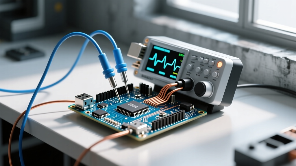
When the code and multimeter fail you, you need to see the digital waveforms. Connect a USB logic analyzer (like a Saleae Logic 8 or a budget DSLogic Plus) to SDA, SCL, and GND. Use software like PulseView (Sigrok) or the Saleae Logic 2 software. Decode the I2C protocol directly in the software. Look for:
- Missing ACK bits: The 9th clock cycle where the receiver should pull SDA low. If it stays high, you have a NACK.
- Rounded edges: If the SDA rise time looks like a shark fin instead of a square wave, your bus capacitance is too high. Shorten the wires or lower the pull-up resistor value.
I2C Arduino FAQ: Troubleshooting and Edge Cases
Why does my I2C Arduino bus lock up randomly during operation?
Random lockups are usually caused by electrical noise pulling the SCL line low right as the master releases it, causing the master and slave to lose clock synchronization (the slave thinks it's still in the middle of a byte). The master will then wait forever for the bus to clear. To fix this in software, implement a bus recovery routine that manually toggles the SCL pin as a standard GPIO 9 times to force the slave to release the SDA line, followed by a Wire.end() and Wire.begin() reset.
Can I connect a 5V Arduino I2C bus directly to a 3.3V sensor?
No. While some 3.3V sensors are 5V tolerant on their I2C pins, many are not. Sending 5V logic into a 3.3V microcontroller's SDA pin will eventually destroy the input protection diodes. Use a bidirectional logic level converter (like a BSS138 MOSFET-based breakout board from SparkFun or Adafruit) to safely shift the 5V Arduino signals down to 3.3V for the sensor.
How many devices can I actually daisy-chain on one I2C bus?
While the 7-bit addressing scheme allows for 128 theoretical addresses (minus reserved ones), the practical limit is usually 10 to 15 devices. The bottleneck is not the address space, but the 400pF bus capacitance limit and address collisions. Many cheap sensors share the exact same hardcoded I2C address with no hardware pins to change it, forcing you to use an I2C multiplexer (like the TCA9548A) to segment the bus.
What are the exact I2C pins on the Arduino Uno and ESP32?
On the classic Arduino Uno (ATmega328P), the hardware I2C pins are strictly A4 (SDA) and A5 (SCL). On the ESP32, the default hardware I2C pins are GPIO 21 (SDA) and GPIO 22 (SCL). However, the ESP32 features a GPIO matrix that allows you to map the I2C peripheral to almost any digital pin using Wire.begin(SDA_PIN, SCL_PIN), though sticking to the defaults avoids software-emulated I2C overhead.