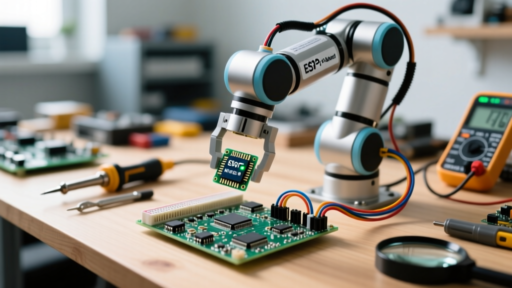

The Architecture of a Networked Manipulator
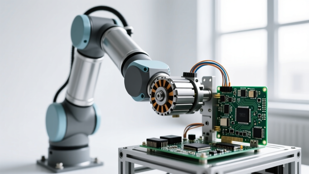
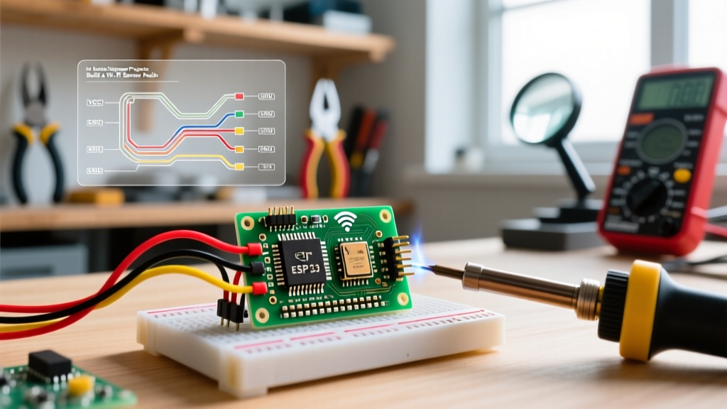
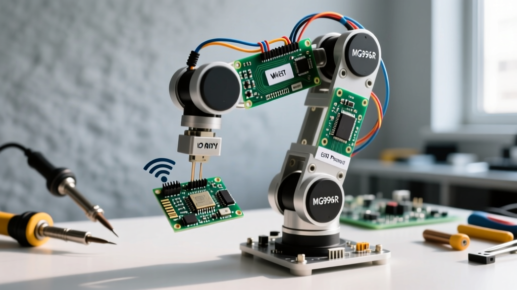
Transitioning a desktop robotics project into a fully connected IoT device requires more than just slapping a Wi-Fi module onto a breadboard. When designing an IoT-connected diy robot arm, the primary engineering challenges revolve around power distribution, real-time network latency, and pulse-width modulation (PWM) stability. In this guide, we will architect a 4-Degree-of-Freedom (4-DOF) robotic manipulator powered by an ESP32, utilizing the MQTT protocol for sub-50ms command latency and real-time telemetry streaming.
Why ESP32 and MQTT over Wi-Fi HTTP?
Many beginner tutorials rely on HTTP REST APIs to control servos. This is a critical mistake for robotics. HTTP introduces handshake overhead and variable latency that can cause a robot arm to stutter or overshoot its target coordinates. MQTT (Message Queuing Telemetry Transport) operates over a persistent TCP connection, allowing for instantaneous publish/subscribe messaging. Furthermore, the ESP32's dual-core architecture allows us to pin the Wi-Fi and MQTT stack to Core 0, while dedicating Core 1 exclusively to inverse kinematics calculations and hardware PWM generation, preventing network interrupts from jittering the servos.
Bill of Materials: Sourcing the Right Actuators
The mechanical foundation of your diy robot arm dictates its payload capacity and precision. While micro-servos like the SG90 are fine for camera mounts, a functional manipulator requires metal-gear servos capable of handling dynamic loads without stripping teeth.
| Component | Model / Specification | Key Metric | Est. Price |
|---|---|---|---|
| Microcontroller | ESP32-WROOM-32 DevKit | Dual-Core 240MHz, 520KB SRAM | $6.50 |
| Base & Shoulder Servos | TowerPro MG996R (x2) | 13kg-cm Torque, 2.5A Stall | $24.00 |
| Elbow & Wrist Servos | TowerPro MG90S (x2) | 2.2kg-cm Torque, 0.8A Stall | $16.00 |
| Power Supply | Mean Well LRS-50-5 | 5V 10A Enclosed SMPS | $18.50 |
| Logic Level Shifter | 74AHCT125 (Optional) | 3.3V to 5V PWM Signal | $2.00 |
According to the official TowerPro MG996R datasheet, the stall current can spike to 2.5A per servo. If your arm experiences a mechanical bind or sudden acceleration, two shoulder servos could draw 5A simultaneously. This necessitates a robust 10A power supply rather than a standard USB wall wart.
Mechanical Assembly and Power Distribution Pitfalls
The most common failure mode in DIY IoT robotics is the 'brownout reset.' When servos draw peak current, the voltage on the 5V rail can dip below 4.8V for a few milliseconds. While this won't harm the servos, the ESP32's internal brownout detector (BOD) will instantly trigger a hardware reset, dropping your MQTT connection and leaving the arm limp.
Solving the Brownout Failure Mode
To stabilize the power delivery network (PDN), you must separate the logic power from the motor power. Wire the 5V 10A Mean Well supply directly to a heavy-duty terminal block. From there, run thick 18AWG silicone wires to the servos. For the ESP32, use a separate buck converter (like the LM2596) stepped down to exactly 5.0V, or power it via the 3.3V pin using an AMS1117 regulator.
Expert Tip: Solder a 4700µF 10V electrolytic capacitor and a 0.1µF ceramic capacitor in parallel directly across the main 5V servo terminal block. The electrolytic capacitor acts as a local energy reservoir to handle low-frequency current spikes, while the ceramic capacitor shunts high-frequency PWM noise away from the ESP32's sensitive RF antenna.
Firmware Development: Hardware PWM and MQTT Payloads
Standard Arduino `Servo.h` libraries rely on software interrupts, which conflict with the ESP32's Wi-Fi radio interrupts. This results in severe servo jitter. Instead, we must use the ESP32's native LED Control (LEDC) peripheral to generate hardware-backed 50Hz PWM signals. The Espressif LEDC API documentation details how to configure the timer to output a precise 50Hz frequency with a 16-bit resolution, giving us microsecond-level control over the servo pulse width.
Structuring the JSON Telemetry Packet
For the IoT dashboard to render the arm's position in real-time, the ESP32 must publish telemetry at roughly 10Hz. We use a lightweight JSON structure to minimize payload size over the network.
{
  'device_id': 'flux_arm_01',
  'uptime_ms': 459201,
  'joints': {
    'base': 90.5,
    'shoulder': 45.2,
    'elbow': 110.0,
    'wrist': 15.8
  },
  'voltage': 5.04,
  'rssi': -42
}
By monitoring the voltage and rssi (Received Signal Strength Indicator) fields, your dashboard can trigger automated alerts if the Wi-Fi signal degrades or the power supply begins to sag under heavy mechanical loads.
Network Latency and Safety Interlocks
When controlling a diy robot arm over a network, packet loss is inevitable. If you are sending absolute coordinate commands via MQTT, a dropped packet might cause the arm to skip a waypoint and violently collide with your desk. To prevent this, implement a software velocity limiter in the ESP32 firmware. Even if the MQTT broker delivers five rapid commands at once, the firmware's interpolation loop should only advance the servo positions by a maximum of 2 degrees per 20ms tick.
Furthermore, configure your MQTT topics with appropriate Quality of Service (QoS) levels. As outlined in the HiveMQ MQTT Essentials guide, QoS 1 guarantees delivery but requires an acknowledgment handshake. Use QoS 1 for critical safety commands (like an emergency stop), but stick to QoS 0 for high-frequency telemetry to prevent network congestion and queue buildup.
Implementing a Network Watchdog
What happens if the router reboots? Your ESP32 will lose its MQTT connection. You must implement a network watchdog timer in your code. If the ESP32 does not receive a 'heartbeat' command from your IoT dashboard within 3 seconds, the firmware should automatically transition the arm into a 'safe sleep' state, slowly lowering the wrist and elbow joints to a resting position using gravity-assisted easing, rather than abruptly cutting power to the servos.
Final Calibration and Dashboard Integration
Once the hardware is assembled and the firmware is flashing, connect your ESP32 to a cloud broker like AWS IoT Core, Mosquitto, or HiveMQ Cloud. Use a web-based MQTT client or a custom Node-RED dashboard to publish JSON commands to the robot/arm/flux_arm_01/cmd topic. By combining robust power distribution, hardware-accelerated PWM, and a properly structured MQTT telemetry pipeline, you elevate a simple desktop toy into a highly responsive, industrial-grade IoT prototype.