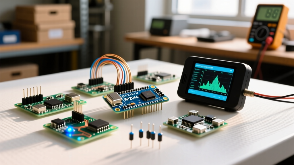
The fundamental difference between Raspberry Pi and Arduino is architectural: Arduino is a bare-metal microcontroller executing a single loop in real-time with microsecond precision and milliwatt power draw, while Raspberry Pi is a single-board computer (SBC) running a full Linux operating system, capable of multitasking, computer vision, and heavy network routing, but burdened by boot times and watt-level power consumption.
If you are trying to decide which board to buy for an embedded project, stop looking at spec sheets and look at your power source and timing requirements. Below is a decision-forward breakdown, a concrete reference build, and the exact debugging steps for when you inevitably try to wire them together.
The Architectural Divide: Microcontroller vs. SBC
To understand the practical difference between Raspberry Pi and Arduino on the workbench, you have to look past the processor speed and look at the execution environment. An Arduino (even a modern ESP32-based one) runs your C++ code directly on the hardware. When you tell a pin to go HIGH, it happens in nanoseconds. A Raspberry Pi runs your Python or C code on top of a Linux kernel. The OS schedules tasks, manages memory, and handles interrupts, meaning a GPIO toggle can be delayed by milliseconds if the CPU is busy writing to an SD card.
| Feature | Arduino Nano ESP32 (Microcontroller) | Raspberry Pi 5 4GB (SBC) |
|---|---|---|
| Execution Environment | Bare-metal RTOS / Arduino Core | Linux (Debian-based Bookworm) |
| Boot Time | Instant (~50ms to first instruction) | 15 to 45 seconds (OS load) |
| Real-Time Determinism | Microsecond precision (Hardware interrupts) | Unpredictable (OS task scheduling jitter) |
| Active Power Draw | ~65mA (approx. 210mW at 3.3V) | ~600mA to 1.2A (3W to 6W at 5V) |
| Deep Sleep Power | ~8µA (Months on a LiPo cell) | Not natively supported (Requires external power gating) |
| True 2026 Entry Cost | ~$21 (Board only, USB-C powers it) | ~$85 ($60 board + $15 active cooler + $10 27W PSU) |
The Decision Tree: Which Board Should You Actually Buy?
Do not default to the Raspberry Pi just because you are more comfortable writing Python. Use this decision path to select the right tool for the job.
- IF your project requires a camera, machine learning inference, or hosting a local web database → Choose Raspberry Pi 5.
- IF your project needs to run on a battery for more than 48 hours without a massive LiFePO4 pack → Choose Arduino.
- IF you are reading high-frequency encoder pulses or generating precise PWM motor signals → Choose Arduino.
- IF your project is a standard IoT sensor node (temperature, humidity, MQTT publishing) → Choose Arduino.
Reference Build: Low-Power IoT Environmental Node
To ground this comparison in reality, let us build a networked environmental sensor. We will use the Arduino Nano ESP32 as the edge node, reading a BME280 sensor over I2C. This build highlights why the microcontroller wins here: it can deep-sleep between reads, sipping microamps, whereas a Pi would burn watts just idling.
Parts List & Exact Variants
- MCU: Arduino Nano ESP32 (Official ABX00092 variant, ~$21)
- Sensor: Adafruit BME280 I2C/SPI Breakout (Product ID 2652, ~$19)
- Wiring: 26 AWG silicone stranded wire, 4-pin JST-PH connector
- Power: 3.7V 1200mAh LiPo with standard micro-JST plug
Pin Mapping Table
| BME280 Breakout Pin | Arduino Nano ESP32 Pin | Notes |
|---|---|---|
| VIN | 3V3 | Do NOT use 5V; the BME280 is strictly 3.3V logic. |
| GND | GND | Common ground required. |
| SCK (SCL) | A5 (GPIO 19) | Default I2C Clock for Nano ESP32. |
| SDI (SDA) | A4 (GPIO 18) | Default I2C Data for Nano ESP32. |
Difficulty Rating: 2/5 (Solderless breadboard or basic JST crimping)
Compilable Firmware: Arduino Nano ESP32 BME280 Reader
The following C++ code targets the Arduino Nano ESP32 specifically. It includes explicit pin definitions, I2C initialization, and robust error handling to prevent silent failures if the sensor is disconnected. You will need the Adafruit_BME280 and Adafruit_Sensor libraries installed via the Arduino Library Manager.
#include <Wire.h>
#include <Adafruit_Sensor.h>
#include <Adafruit_BME280.h>

// Explicit Pin Definitions for Arduino Nano ESP32
#define I2C_SDA_PIN 18  // Physical pin A4
#define I2C_SCL_PIN 19  // Physical pin A5
#define SEALEVELPRESSURE_HPA (1013.25)
#define SENSOR_I2C_ADDR 0x76 // Adafruit breakouts default to 0x77, some clones use 0x76

Adafruit_BME280 bme;

void setup() {
  Serial.begin(115200);

  // Wait for serial monitor to connect (useful for debugging)
  unsigned long startMillis = millis();
  while (!Serial && (millis() - startMillis < 3000)) {
    delay(10);
  }

  Serial.println("Initializing I2C bus...");

  // Initialize I2C with explicit pins and 100kHz clock
  Wire.begin(I2C_SDA_PIN, I2C_SCL_PIN);

  // Error Handling: Verify sensor presence
  if (!bme.begin(SENSOR_I2C_ADDR, &Wire)) {
    Serial.println("FATAL ERROR: Could not find a valid BME280 sensor.");
    Serial.println("Check: 1. Wiring (SDA/SCL swapped?) 2. I2C Address (0x76 vs 0x77) 3. 3.3V Power.");

    // Blink onboard LED to indicate hardware fault without needing serial
    pinMode(LED_BUILTIN, OUTPUT);
    while (1) {
      digitalWrite(LED_BUILTIN, HIGH);
      delay(100);
      digitalWrite(LED_BUILTIN, LOW);
      delay(100);
    }
  }

  Serial.println("BME280 initialized successfully. Starting reads.");
}

void loop() {
  float temperature = bme.readTemperature();
  float humidity = bme.readHumidity();
  float pressure = bme.readPressure() / 100.0F;

  // Sanity check for NaN (Not a Number) returns caused by bus noise
  if (isnan(temperature) || isnan(humidity) || isnan(pressure)) {
    Serial.println("ERROR: Sensor read returned NaN. I2C bus noise suspected.");
  } else {
    Serial.printf("Temp: %.2f C | Humidity: %.2f %% | Pressure: %.2f hPa\n",
                  temperature, humidity, pressure);
  }

  // In a real battery build, you would use esp_deep_sleep_start() here
  delay(5000);
}
Debugging Hybrid Setups: Resolving I2C Bus Crashes
Many advanced makers eventually combine the two platforms, using an Arduino for real-time motor control and a Raspberry Pi for high-level path planning, bridging them via I2C. When the Pi acts as the I2C Master and the Arduino acts as the Slave, you will inevitably hit this exact Python error on the Pi:
OSError: [Errno 121] Remote I/O error
This error means the Pi's Linux I2C driver sent a clock pulse, but the Arduino either NAK'd (Not Acknowledged) the address, missed the clock stretch, or the physical bus collapsed. If your hybrid build fails, check these three things in this exact order:
- Logic Level Mismatch (The Silent Killer): The Raspberry Pi is strictly a 3.3V device. If you connect it to a 5V Arduino Uno R3, the Pi's GPIO pins will be back-fed 5V, potentially destroying the Pi's SoC. Even if you use a 3.3V Arduino Nano ESP32, you must ensure both boards share a common Ground. Fix: Always use a bidirectional logic level shifter (like the BSS138-based Adafruit 757) when mixing 5V and 3.3V boards.
- Missing Pull-Up Resistors: I2C is an open-drain protocol. It requires pull-up resistors to pull the SDA and SCL lines HIGH. While the Adafruit BME280 has onboard 10k pull-ups, raw Arduino-to-Pi wiring often lacks them. Fix: Solder 4.7kΩ resistors between SDA and 3.3V, and SCL and 3.3V.
- Arduino Clock Stretching Timeout: If the Arduino is busy executing a heavy interrupt (like reading a rotary encoder) when the Pi requests data, the Arduino tries to 'stretch the clock' (hold SCL low) to buy time. The Raspberry Pi's hardware I2C controller has a notoriously short timeout for clock stretching and will just throw the
[Errno 121]error and abort. Fix: Use the Pi's software I2C fallback (i2c-gpiooverlay in config.txt) which handles clock stretching gracefully, or ensure the Arduino's I2C ISR (Interrupt Service Routine) is under 50 microseconds.
Scaling the Architecture: Extend or Simplify
Once your baseline sensor node or hybrid bridge is working, you need to know how to adapt the design for production or budget constraints.
How to Simplify the Build
If you are blowing your budget or running out of flash memory, strip the wireless stack. Drop the ESP32 and switch to an ATtiny85 (~$2). Remove the I2C sensor and use a simple analog thermistor with a voltage divider. You lose WiFi and digital precision, but you drop the BOM cost to under $4 and the power draw to single-digit microamps, allowing a single CR2032 coin cell to run the node for a year.
How to Extend the Build
If you need to scale from one sensor to a whole-house array, do not try to make the Arduino handle the database. Extend the architecture by introducing a Raspberry Pi Zero 2 W as a local MQTT broker (using Mosquitto). Flash your Arduino Nano ESP32 nodes to publish JSON payloads to the Pi's local IP. The Pi then handles the heavy lifting: logging to an InfluxDB time-series database, running Grafana dashboards, and triggering Home Assistant automations. This leverages the exact strengths of both platforms—the Arduino handles the real-time, low-power edge sensing, while the Pi handles the networked data aggregation.