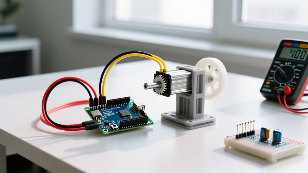
The Direct Answer: Building an Arduino RPM Sensor
To build a reliable Arduino RPM sensor, use an A3144 Hall effect sensor (commonly sold as the KY-003 module) paired with a small neodymium magnet. Wire the sensor's digital output to a hardware interrupt pin (D2 or D3 on the Arduino Nano V3). Instead of using delay() or polling, calculate the RPM by measuring the microsecond delta between falling edges using an Interrupt Service Routine (ISR). This approach guarantees accurate readings even at high speeds (up to 10,000+ RPM) without blocking your main loop.
digitalRead() inside loop()) for RPM measurement. If your main loop takes 5ms to execute, you will completely miss magnet passes on any motor spinning above 3,000 RPM. Hardware interrupts are mandatory for precision.
Sensor Selection: Hall Effect vs. Optical vs. Inductive
Before wiring anything, you need to select the right transducer for your environment. While optical sensors are popular in hobbyist kits, they fail in dusty or oily environments. Below is a data-dense comparison of the four common RPM sensing technologies to help you choose the right module for your specific build.
| Sensor Type | Common Module | Max Switching Freq | Signal Edge Sharpness | Environmental Robustness | Avg. Price (2026) |
|---|---|---|---|---|---|
| Hall Effect (Switch) | KY-003 (A3144) | ~20 kHz | Excellent (Digital) | High (Ignores dust/oil) | $1.50 - $2.50 |
| Optical (Slotted) | FC-03 / LM393 | ~50 kHz | Good (Analog/Digital) | Low (Fails if dusty) | $2.00 - $3.50 |
| Inductive Proximity | LJ12A3-4-Z/BX | ~2 kHz | Fair (Requires Schmitt) | Extreme (Industrial) | $8.00 - $12.00 |
| Magnetic Reed Switch | KY-025 | ~200 Hz | Poor (Severe bounce) | Medium | $1.00 - $1.50 |
For 90% of DIY motor, fan, and small engine projects, the KY-003 Hall Effect module is the correct choice. It includes an onboard LM393 comparator and a 10k pull-up resistor, meaning it outputs a clean 0V/5V square wave directly to the microcontroller. According to SparkFun's Hall Effect Sensor Tutorial, the A3144 is a unipolar switch, meaning it only triggers when exposed to a specific magnetic pole (South), which naturally prevents double-triggering from a single magnet.
Parts List and Pin Mapping
This guide targets the Arduino Nano V3 (ATmega328P). The Nano is preferred over the Uno for embedded motor projects due to its smaller footprint and identical interrupt architecture. The code provided relies on the Arduino attachInterrupt() API.
Bill of Materials
- Microcontroller: Arduino Nano V3 (ATmega328P, 5V/16MHz variant)
- Sensor: KY-003 Hall Effect Module (A3144-based)
- Magnet: 6x3mm Neodymium (N42 grade or higher)
- Wiring: 22 AWG stranded silicone wire (3 lengths)
- Mounting: Hot glue or 2-part epoxy (for magnet retention)
Pin Mapping Table
| Arduino Nano Pin | KY-003 Module Pin | Wire Color | Notes & Constraints |
|---|---|---|---|
| D2 | DO (Digital Out) | Yellow | Must be a hardware interrupt pin (INT0). |
| 5V | VCC | Red | Do not use 3.3V; the LM393 needs 4.5V minimum. |
| GND | GND | Black | Share common ground with the motor driver if applicable. |
Wiring and Physical Setup
Physical placement of the magnet and sensor is where most RPM builds fail. Follow these steps to ensure clean signal edges.
- Prepare the Rotor: Clean the surface of your spinning shaft or fan hub with isopropyl alcohol. Glue the 6x3mm neodymium magnet to the rotor. Crucial: The A3144 triggers on the South pole. Mark the South pole of your magnet with a Sharpie before gluing, and ensure the South pole faces outward.
- Set the Air Gap: Mount the KY-003 sensor so the face of the black A3144 chip is exactly 2mm to 4mm from the magnet's path. If the gap is >5mm, the sensor will miss passes at high speeds. If it's <1mm, mechanical vibration will cause the magnet to strike the sensor.
- Wire the Module: Connect DO to D2, VCC to 5V, and GND to GND. Do not use the AO (Analog Out) pin on the KY-003; it outputs a varying voltage based on magnetic field strength, which is useless for digital RPM timing.
- Verify the Signal: Before attaching the motor, power the Nano and manually swipe the South pole of the magnet past the sensor. The onboard LED on the KY-003 module should flash sharply. If it stays on, your magnet is too close or you are using the wrong pole.
Interrupt-Driven RPM Code
The following C++ code is fully compilable for the Arduino Nano V3. It uses micros() for high-resolution timing and includes a software debounce filter to ignore electrical noise, as well as a timeout function to correctly report 0 RPM when the motor stops.
// Arduino RPM Sensor - Hall Effect Interrupt Code
// Target Board: Arduino Nano V3 (ATmega328P)

const int HALL_SENSOR_PIN = 2; // Hardware interrupt pin (INT0)
const int MAGNET_COUNT = 1;    // Number of magnets on the rotor

// Volatile variables shared with ISR
volatile unsigned long lastPulseMicros = 0;
volatile unsigned long pulseDeltaMicros = 0;
volatile bool newPulse = false;

// Debounce threshold (ignore bounces shorter than 200us)
const unsigned long DEBOUNCE_US = 200;
// Timeout (if no pulse for 1.5 seconds, assume motor is stopped)
const unsigned long TIMEOUT_US = 1500000;

void setup() {
  Serial.begin(115200);
  // Use internal pull-up as a failsafe, though KY-003 has its own
  pinMode(HALL_SENSOR_PIN, INPUT_PULLUP);

  // Attach interrupt on FALLING edge (0V transition)
  attachInterrupt(digitalPinToInterrupt(HALL_SENSOR_PIN), hallISR, FALLING);

  Serial.println("Arduino RPM Sensor Initialized.");
}

void loop() {
  unsigned long currentRunMicros = micros();
  float rpm = 0.0;

  // Check if motor has stopped (Timeout logic)
  if (currentRunMicros - lastPulseMicros > TIMEOUT_US) {
    pulseDeltaMicros = 0; // Force zero state
    newPulse = false;
  }

  if (newPulse && pulseDeltaMicros > 0) {
    // RPM = (60 seconds * 1,000,000 microseconds) / (delta * magnets)
    rpm = 60000000.0 / (pulseDeltaMicros * MAGNET_COUNT);

    Serial.print("RPM: ");
    Serial.println(rpm, 1); // Print with 1 decimal place

    newPulse = false; // Reset flag
  }

  // Main loop is free for other tasks (OLED updates, PID control, etc.)
}

// Interrupt Service Routine (ISR)
void hallISR() {
  unsigned long currentMicros = micros();
  unsigned long delta = currentMicros - lastPulseMicros;

  // Software debounce: ignore signal chatter
  if (delta > DEBOUNCE_US) {
    pulseDeltaMicros = delta;
    lastPulseMicros = currentMicros;
    newPulse = true;
  }
}
Debugging: Fixing Jitter and Porting Errors
If your serial monitor shows erratic values, negative numbers, or fails to compile when you upgrade your hardware, use this decision tree to isolate the fault.
The First Three Things to Check
- Magnet Polarity & Alignment: If the RPM reads exactly half of what it should be, your magnet is tumbling and presenting both North and South poles to a sensor that is accidentally acting in bipolar mode, or you have two magnets and forgot to update
MAGNET_COUNT. Verify the South pole is strictly facing the sensor. - Floating Pin Noise: If you see massive RPM spikes (e.g., jumping from 1,200 to 60,000) while the motor is off, your interrupt pin is floating. Ensure you are using
INPUT_PULLUPand that the wire between D2 and the KY-003 is not running parallel to the motor's power cables, which induces EMI. - Interrupt Pin Mapping: If the code compiles but reads 0 RPM, verify you are using D2 or D3. On the Nano V3, only D2 (INT0) and D3 (INT1) support hardware interrupts. Pin D4 will silently fail to trigger the ISR.
Exact Error String: Porting to ESP32
A common failure mode occurs when makers take this exact Nano code and flash it to an ESP32 (like the ESP32-WROOM-32 DevKit). The compiler will throw the following exact error string:
error: 'IRAM_ATTR' attribute missing on ISR
or at runtime:
Guru Meditation Error: Core 1 panic'ed (Interrupt wdt timeout on CPU 1)
The Fix: The ESP32 runs on a dual-core FreeRTOS architecture. ISRs must be explicitly placed in the Instruction RAM (IRAM) to execute fast enough. Change your ISR declaration from void hallISR() to void IRAM_ATTR hallISR(). Additionally, change the timeout variable type to volatile uint32_t to prevent 32-bit overflow issues specific to the ESP32's micros() implementation.
Extending and Simplifying the Build
Depending on your end goal, you may need to strip this project down or scale it up.
How to Simplify (Frequency Counter Mode)
If you don't need actual RPM and just want to know if a motor is spinning above a certain threshold (e.g., a cooling fan fail-safe), strip out the micros() math entirely. Simply increment a volatile int pulseCount inside the ISR, and check if pulseCount > 50 every second in the main loop. This reduces CPU overhead to near zero and eliminates floating-point math errors.
How to Extend (OLED Dashboard & PID)
To turn this into a standalone tachometer, add an I2C OLED display (SSD1306, 128x64). Wire SDA to A4 and SCL to A5 on the Nano. Use the Adafruit_SSD1306 library to render the RPM. Because our ISR is non-blocking, the OLED refresh rate won't interfere with the pulse timing. For closed-loop motor control, feed the rpm variable directly into a PID library (like Arduino-PID-Library) as your process variable (PV) to maintain a constant speed under varying mechanical loads.