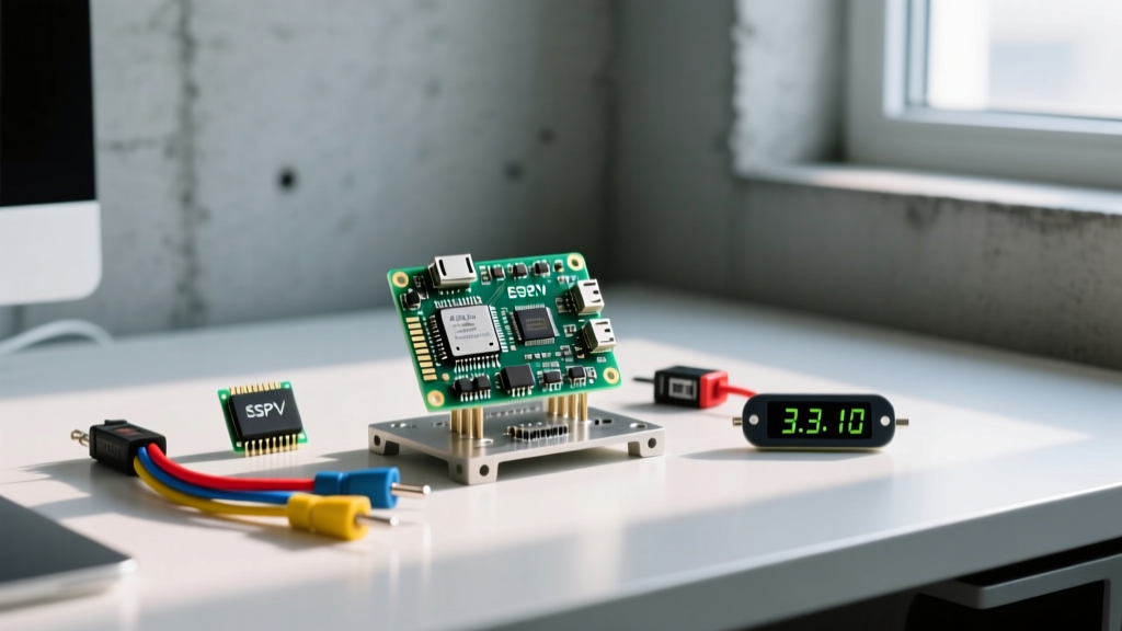
The Arduino Relais Shield (frequently searched as 'relais' by European makers, but functionally identical to the standard Relay Shield) is the fastest way to switch high-voltage or high-current loads without breadboarding raw transistors and flyback diodes. Whether you are using the official Arduino Relay Shield v3 or the ubiquitous generic 4-channel 5V modules, the core principle is the same: a low-voltage GPIO signal energizes a 5V coil, which physically pulls a contactor to switch an isolated AC or DC load.
This guide provides the exact pin mappings, a safe mains-wiring procedure, and a complete, compilable control sketch targeting the Arduino Uno R3 and R4 Minima. We will also cover the specific hardware and software failure modes that cause 90% of relay shield debugging headaches.
Hardware Overview & Parts List
Before writing code, verify exactly which shield variant you have on your bench. The pinouts differ significantly between the official and generic clones.
Required Parts
- Microcontroller: Arduino Uno R3 (ATmega328P) or Uno R4 Minima (Renesas RA4M1). The code below targets the Uno R3/R4 form factor.
- Shield Variant A (Generic): 4-Channel 5V Relay Shield (typically uses Songle SRD-05VDC-SL-C relays). Cost: ~$8-$12.
- Shield Variant B (Official): Arduino Relay Shield v3 (uses Omron G5LE-14 relays). Cost: ~$22-$28.
- Power Supply: 7-12V DC barrel jack power supply (2A minimum to prevent brownouts when all 4 coils energize simultaneously).
- Load: 12V DC solenoid or 120V AC lamp (for testing).
Relay Specification Sheet (Generic 4-Channel)
| Parameter | Typical Value (Songle SRD-05VDC) | Practical Limit |
|---|---|---|
| Coil Voltage | 5V DC | Draws ~70mA per relay |
| Contact Rating (Resistive) | 10A @ 250VAC / 30VDC | Derate to 5A for inductive loads (motors) |
| Dielectric Strength | 4000V RMS (Coil to Contact) | Provides safe galvanic isolation |
| Operate Time | ~10ms | Not suitable for high-frequency PWM |
Pin Mapping and Safe Load Wiring
The most common mistake when stacking a relais shield is assuming the pinout is standardized. It is not. Below is the mapping for the two most common variants.
| Relay Channel | Generic 4-Channel Shield | Official Arduino Shield v3 |
|---|---|---|
| Relay 1 | Digital Pin 4 | Digital Pin 4 |
| Relay 2 | Digital Pin 5 | Digital Pin 7 |
| Relay 3 | Digital Pin 6 | Digital Pin 8 |
| Relay 4 | Digital Pin 7 | Digital Pin 12 |
Wiring the Load (COM, NO, NC)
Each relay channel has three screw terminals:
- COM (Common): The moving contact. This is where your load's live/hot wire connects.
- NO (Normally Open): The circuit is broken until the Arduino pulls the pin HIGH (or LOW, depending on the board's driver logic). Connect your load's return wire here for standard 'turn on when triggered' operation.
- NC (Normally Closed): The circuit is complete until the relay triggers. Use this for fail-safe applications (e.g., a heating element that must shut off if the Arduino crashes).
Compilable Control Code (Targeting Uno R3 / R4)
This sketch targets the Generic 4-Channel Shield (Pins 4, 5, 6, 7). It includes explicit pin definitions, safe startup states (ensuring all relays are OFF before the Arduino finishes booting), and a serial debugging loop to verify state changes.
// Target Board: Arduino Uno R3 / R4 Minima
// Shield: Generic 4-Channel 5V Relais Shield

#define RELAY_1_PIN 4
#define RELAY_2_PIN 5
#define RELAY_3_PIN 6
#define RELAY_4_PIN 7

#define RELAY_ON  HIGH  // Change to LOW if your shield uses active-low optocouplers
#define RELAY_OFF LOW

const int relayPins[] = {RELAY_1_PIN, RELAY_2_PIN, RELAY_3_PIN, RELAY_4_PIN};
const int numRelays = 4;

void setup() {
  Serial.begin(115200);
  while (!Serial && millis() < 2000) {
    // Wait for serial monitor on native USB boards (R4), timeout after 2s
  }

  Serial.println("[INIT] Configuring Relais Shield Pins...");

  // CRITICAL: Set pins to OUTPUT and OFF state immediately to prevent
  // floating GPIOs from accidentally energizing coils during boot.
  for (int i = 0; i < numRelays; i++) {
    pinMode(relayPins[i], OUTPUT);
    digitalWrite(relayPins[i], RELAY_OFF);
  }

  Serial.println("[INIT] All relays safely de-energized.");
}

void loop() {
  // Sequence test: Turn on each relay for 2 seconds, then verify state
  for (int i = 0; i < numRelays; i++) {
    energizeRelay(i, true);
    delay(2000);
    energizeRelay(i, false);
    delay(500);
  }

  Serial.println("[CYCLE] Sequence complete. Waiting 5 seconds...\n");
  delay(5000);
}

void energizeRelay(int index, bool state) {
  if (index < 0 || index >= numRelays) {
    Serial.println("[ERR] Relay index out of bounds!");
    return;
  }

  int pin = relayPins[index];
  digitalWrite(pin, state ? RELAY_ON : RELAY_OFF);

  // Read back the output register to verify the MCU actually set the pin
  int actualState = digitalRead(pin);
  int expectedState = state ? RELAY_ON : RELAY_OFF;

  if (actualState == expectedState) {
    Serial.print("[OK] Relay ");
    Serial.print(index + 1);
    Serial.print(" (Pin ");
    Serial.print(pin);
    Serial.print(") -> ");
    Serial.println(state ? "ENERGIZED" : "DE-ENERGIZED");
  } else {
    // Exact error string for debugging hardware/pin conflicts
    Serial.println("[ERR] RELAY_STATE_MISMATCH: Pin " + String(pin) + " failed to latch.");
  }
}
Debugging: First Three Things to Check When It Fails
When your load doesn't turn on, don't immediately rewrite your code. Hardware and power delivery issues account for the vast majority of relay shield failures. Here is your diagnostic decision tree.
1. The 'Click but No Power' Fault
Symptom: You hear the mechanical click of the relay, and the LED on the shield turns on, but your load (lamp, motor) receives no power.
Fix: You have wired the load to the NC (Normally Closed) terminal instead of NO (Normally Open), or you have broken the neutral/ground return path. Use your multimeter in continuity mode (with power OFF) to verify that COM and NO are open when the relay is off, and shorted when you manually apply 5V to the coil.
2. The Brownout Reset Loop
Symptom: The Arduino resets (pins 13 LED flashes) the exact moment the first or second relay clicks. The serial monitor disconnects.
Fix: Each relay coil draws ~70mA. Four relays pulling 280mA simultaneously, plus the ATmega328P and shield LEDs, will exceed the 500mA limit of a standard USB port, causing a brownout. Solution: Power the Arduino via the barrel jack with a 9V/2A wall adapter, bypassing the USB polyfuse.
3. Software Pin Conflicts and I2C Confusion
Symptom: You copied code from a tutorial and get a compiler error, or an I2C scanner sketch returns [ERR] I2C Scanner: No devices found at 0x20.
Ranked Causes:
- You have a GPIO shield, not an I2C shield. Standard 4-channel relais shields do not use the Wire/I2C library. They use direct
digitalWrite()commands. RemoveWire.hfrom your sketch. - SPI/UART Conflict. If you are using an Ethernet shield or an SD card module stacked under the relais shield, Pins 4, 11, 12, and 13 are already claimed by the SPI bus. The Generic shield uses Pin 4 (conflict!), and the Official shield uses Pin 12 (conflict!). You must bend the relay shield pin and jumper it to an unused analog pin (e.g., A0/A1) configured as a digital output.
- Missing Pull-ups. If you actually do have a specialized I2C relay shield (like the Seeed Studio Grove 2-Channel), ensure the I2C pull-up resistors on the shield are jumpered closed, as the Uno R4 Minima does not always enable internal pull-ups for external shields reliably.
Extending or Simplifying the Build
Depending on your project's final deployment environment, a raw relais shield might be overkill—or underkill.
How to Simplify (The Single-Channel Alternative)
If you only need to switch one 120V AC load, drop the $15 shield. Buy a single 5V relay module with an optocoupler ($2-$4). Wire the VCC to the Arduino's 5V pin, GND to GND, and the IN pin to any digital output. This saves vertical stack height and leaves your SPI/UART pins completely free for sensors.
How to Extend (Handling Inductive Kickback)
While most generic shields include a small 1N4148 flyback diode across the coil to protect the Arduino's GPIO pins, they do not protect the contacts from the load's inductive spike. If you are switching large DC motors, solenoids, or transformers, the arcing across the COM/NO contacts will pit and weld them shut within a few hundred cycles.
The Fix: Place an RC snubber network (e.g., 100Ω resistor in series with a 0.1µF X2-rated capacitor) directly across your load's terminals, or use a bidirectional TVS diode. For high-cycle applications (switching more than once per second), abandon the mechanical relais shield entirely and use a Solid State Relay (SSR) module rated for your load.
Frequently Asked Questions (FAQ)
Can I use the Arduino Relais Shield to switch 240V AC directly?
Yes, but with strict caveats. The Songle relays on generic shields are typically rated for 10A at 250VAC. However, this is for resistive loads (like a space heater). If you are switching an inductive load (like an AC motor or compressor), you must derate the relay by at least 50%, meaning a 5A maximum draw. Furthermore, ensure your PCB creepage and clearance distances are adequate; cheap clone shields often have insufficient physical gaps between the high-voltage screw terminals and the low-voltage Arduino header pins.
Why does my Arduino reset every time the relay clicks?
This is almost always a brownout caused by voltage sag. When the relay coil energizes, it draws a sudden inrush current. If you are powering the Arduino via a laptop USB port, the port's overcurrent protection will trip, or the 5V rail will sag below the ATmega328P's brownout detection threshold (typically 2.7V - 4.3V depending on fuse settings), causing a hardware reset. Always use a dedicated 2A+ wall adapter via the DC barrel jack for multi-relay projects.
Do I need flyback diodes if the shield already has them?
You need to understand which flyback diode you are looking at. The diodes mounted on the shield PCB (usually blue or black glass cylinders near the relay coils) protect the Arduino's transistors from the coil's collapse. They do absolutely nothing to protect the relay's internal metal contacts from the arcing caused by the load you are switching. If your load is inductive, you still need a snubber or flyback diode across the load itself.
How do I control a 12V DC motor with this shield?
Wire the 12V power supply's positive terminal to the relay's COM terminal. Wire the NO terminal to the motor's positive lead. Wire the motor's negative lead back to the power supply's ground. Critical addition: You must solder a 1N4007 flyback diode directly across the motor's terminals (stripe facing the 12V positive side) to absorb the reverse voltage spike when the relay opens, preventing the arc from destroying the relay contacts or feeding noise back into your Arduino's power rail.