The MPU6050 sensor is a 6-axis MEMS motion tracking device that combines a 3-axis gyroscope and a 3-axis accelerometer into a single QFN-24 package. While TDK InvenSense designed the silicon, hobbyists almost exclusively interact with it via the ubiquitous blue GY-521 breakout board. The chip outputs strictly digital data over an I2C bus, providing 16-bit signed integers for each axis rather than analog voltages. To get usable physical measurements like degrees-per-second or g-force, you must apply specific scaling factors based on your configured Full Scale Range (FSR).
MPU6050 Sensor Specifications and I2C Wiring
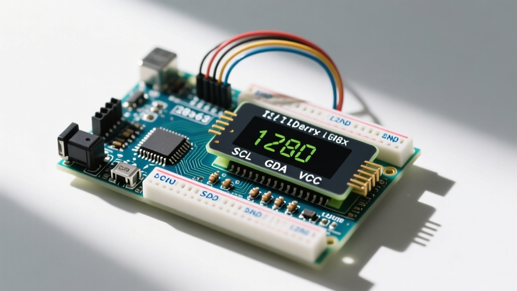
The most common point of failure when wiring the GY-521 breakout is misunderstanding the voltage tolerances. The raw MPU-6050 silicon operates strictly at 3.3V. However, the GY-521 breakout board includes an onboard linear voltage regulator (typically a MIC5205 or similar LDO) and logic-level shifters. This allows you to power the breakout's VCC pin with either 3.3V or 5V, while the I2C data lines (SDA/SCL) are safely pulled up to 3.3V by the board's internal resistors.
I2C Pinout and Wiring Table
| Breakout Pin | Function | Connection / Supply Range | Notes & Bench Tips |
|---|---|---|---|
| VCC | Power Supply | 3.3V to 5.0V DC | Powers the onboard LDO. Do not exceed 5.5V. |
| GND | Ground | Common Ground | Must share a common ground with your MCU. |
| SCL | I2C Clock | MCU SCL Pin | Arduino Uno: A5. ESP32: GPIO 22 (default). |
| SDA | I2C Data | MCU SDA Pin | Arduino Uno: A4. ESP32: GPIO 21 (default). |
| XDA | Aux I2C Data | Leave unconnected | Used for external magnetometers (e.g., HMC5883L). |
| XCL | Aux I2C Clock | Leave unconnected | Used for external magnetometers. |
| AD0 | I2C Address Select | GND or VCC | GND = 0x68. VCC = 0x69. Internal pull-down present. |
| INT | Interrupt Output | MCU Digital Pin | Push-pull, active-high. Useful for DMP data-ready alerts. |
Full Scale Range (FSR) and Sensitivity Data
Before writing code, you must configure the FSR registers. The FSR dictates the maximum measurable limit and the resolution (sensitivity) of the 16-bit output. This data-dense table is critical for your raw-to-unit math conversions.
| Sensor | Full Scale Range (FSR) | Sensitivity (LSB per Unit) | Resolution (16-bit signed) | Register Config (Hex) |
|---|---|---|---|---|
| Accelerometer | ±2g | 16,384 LSB/g | ~0.00006g per bit | 0x00 (AFS_SEL = 0) |
| Accelerometer | ±4g | 8,192 LSB/g | ~0.00012g per bit | 0x08 (AFS_SEL = 1) |
| Accelerometer | ±8g | 4,096 LSB/g | ~0.00024g per bit | 0x10 (AFS_SEL = 2) |
| Accelerometer | ±16g | 2,048 LSB/g | ~0.00048g per bit | 0x18 (AFS_SEL = 3) |
| Gyroscope | ±250 °/s | 131 LSB/°/s | ~0.0076 °/s per bit | 0x00 (FS_SEL = 0) |
| Gyroscope | ±500 °/s | 65.5 LSB/°/s | ~0.0152 °/s per bit | 0x08 (FS_SEL = 1) |
| Gyroscope | ±1000 °/s | 32.8 LSB/°/s | ~0.0305 °/s per bit | 0x10 (FS_SEL = 2) |
| Gyroscope | ±2000 °/s | 16.4 LSB/°/s | ~0.0609 °/s per bit | 0x18 (FS_SEL = 3) |
For balancing robots or drone flight controllers, use ±2g and ±250°/s to maximize resolution, as the physical movements rarely exceed these bounds. For high-vibration environments like RC cars or rocketry, bump the accelerometer to ±8g or ±16g to prevent clipping, even though you lose fine-grained resolution.
The MEMS Sensing Principle and Digital Output
The accelerometer inside the MPU6050 relies on capacitive Micro-Electro-Mechanical Systems (MEMS) technology. It contains a microscopic suspended seismic mass (a proof mass) anchored by flexible silicon tethers. When the chip experiences linear acceleration, the mass deflects from its resting position. This physical displacement changes the distance between the mass and fixed surrounding electrodes, altering the capacitance. The onboard ASIC measures these femtofarad-level capacitance shifts and converts them into a voltage proportional to the g-force applied along the X, Y, and Z axes.
The gyroscope operates on an entirely different physical principle: the Coriolis effect. It utilizes vibrating proof masses driven into continuous oscillation by electrostatic forces. When the chip experiences rotational movement, the Coriolis force acts on the vibrating masses, pushing them orthogonally to their vibration axis. This orthogonal deflection is again measured capacitively. Because the vibration frequency is known and tightly controlled, the magnitude of the Coriolis deflection translates directly into the angular velocity (degrees per second) of the rotation.
Digital Output Architecture
Unlike analog sensors that output a varying voltage (e.g., 0-3.3V) requiring an ADC, the MPU6050 sensor outputs strictly digital data. The internal Analog-to-Digital Converters (ADCs) sample the capacitive changes and store the results in 14 hardware registers as 16-bit signed integers (ranging from -32,768 to +32,767). The MCU reads these registers via the I2C protocol. There is no analog voltage output on the breakout pins; attempting to read SDA or SCL with an analog multimeter will only yield meaningless bus noise.
Converting Raw Registers to Physical Units (The Math)
Reading the I2C registers only gives you a raw 16-bit integer. To convert this into a meaningful physical unit, you must divide the raw value by the Sensitivity Scale Factor (LSB per unit) from the table above. According to the official TDK InvenSense MPU-6050 specification, the math is a simple linear scaling operation.
Acceleration Math (Converting to 'g')
Assuming you configured the accelerometer to the default ±2g range (16,384 LSB/g):
// Read raw 16-bit signed integer from I2C registers
int16_t raw_accel_x = read_register(0x3B);

// Convert to g-force
float accel_x_g = (float)raw_accel_x / 16384.0;

// Convert to m/s^2 (multiply by standard gravity 9.80665)
float accel_x_ms2 = accel_x_g * 9.80665;
Gyroscope Math (Converting to °/s)
Assuming you configured the gyroscope to the default ±250°/s range (131 LSB/°/s):
// Read raw 16-bit signed integer from I2C registers
int16_t raw_gyro_x = read_register(0x43);

// Convert to degrees per second
float gyro_x_dps = (float)raw_gyro_x / 131.0;

// Convert to radians per second (multiply by pi/180)
float gyro_x_rads = gyro_x_dps * 0.0174533;
Calibration and Zero-Offset Scaling
MEMS sensors suffer from manufacturing tolerances that result in a non-zero output even when the sensor is perfectly still (zero-offset error). If your raw Z-axis accelerometer reads 16500 instead of 16384 at rest, your pitch/roll calculations will drift.
Calibration Procedure:
- Mount the sensor on a known level, vibration-free surface.
- Read all 6 axes 100 to 500 times in a loop.
- Calculate the average raw value for each axis.
- For the Z-axis accelerometer, subtract
16384(1g) from the average. For all other axes, the target average is0. - Store these offsets in the MCU's EEPROM and subtract them from every subsequent raw reading before applying the sensitivity divider.
Alternatively, you can bypass MCU math entirely by utilizing the MPU6050's internal Digital Motion Processor (DMP). The DMP can run sensor fusion algorithms (like the Mahony or Madgwick filters) directly on the chip, outputting pre-calculated quaternions via the INT pin. Jeff Rowberg's excellent I2Cdevlib library remains the gold standard for accessing the undocumented DMP features on this chip.
Real-World Interference and Troubleshooting I2C Drops
On the bench, the MPU6050 is highly reliable. In the field, it is prone to specific interference sources that cause I2C bus lockups or noisy data.
1. High-Frequency Mechanical Vibration (Aliasing)
If you mount the MPU6050 near brushless drone motors or 3D printer stepper motors, high-frequency vibrations will alias into your low-frequency measurements, causing the accelerometer to read erratic g-forces. The Fix: Do not just rely on software averaging. Configure the MPU6050's internal Digital Low Pass Filter (DLPF) via Register 26. Setting the DLPF_CFG to 3 (44Hz bandwidth) physically filters out motor noise before it hits the ADC, yielding vastly superior results to software filtering.
2. I2C Bus Capacitance and Pull-Up Resistor Failures
The most common reason an ESP32 or Arduino fails to detect the sensor (returning 0xFF or hanging on Wire.endTransmission()) is improper I2C bus biasing. The GY-521 breakout has weak internal pull-up resistors (often 47kΩ or higher), which are insufficient for reliable 400kHz Fast Mode communication, especially if you have long wires adding parasitic capacitance. According to the NXP I2C Bus Specification, bus capacitance limits rise times.
The Fix: Add external pull-up resistors to the SDA and SCL lines. Use 4.7kΩ resistors tied to 3.3V for standard 100kHz mode. If you are running the bus at 400kHz, drop the pull-ups to 2.2kΩ to ensure the signal edges rise fast enough to meet the I2C timing spec.
3. Magnetic Interference (A Non-Issue)
A frequent misconception among beginners is that nearby motors or magnets will skew the MPU6050's heading calculations. The MPU6050 does not contain a magnetometer. It measures linear acceleration and rotational velocity purely through mechanical and capacitive means. While a strong alternating magnetic field could theoretically induce noise on the I2C traces, the sensor silicon itself is entirely immune to magnetic flux. If your project requires absolute heading relative to magnetic north, you must add a 9-axis chip like the MPU-9250 or a standalone BNO055.
The MPU6050 gyroscope exhibits a zero-rate temperature drift of roughly ±0.02 °/s/°C. If your sensor is mounted near a hot voltage regulator or outdoors in direct sunlight, the changing temperature will cause your integrated yaw angle to drift over time. Always pair the MPU6050 with a magnetometer or GPS for long-duration dead-reckoning, or use the onboard temperature sensor (Register 0x41) to apply software compensation curves.