An lcd display segment is a custom-shaped, electrically isolated liquid crystal electrode that darkens when an alternating voltage is applied, used to render fixed, predefined graphics or digits instead of a programmable pixel matrix. By shifting your user interface from software-rendered pixels to hardware-fixed glass, a segment display changes your circuit by slashing microcontroller RAM usage from kilobytes to absolute zero and dropping display power consumption from milliamps to single-digit microamps. Makers and junior engineers commonly confuse segment LCDs with standard 7-segment LED displays (which use power-hungry discrete light-emitting diodes) or character/dot-matrix LCDs (which use a fixed grid of pixels to draw arbitrary shapes).
The Anatomy of an LCD Display Segment
Unlike an OLED or TFT screen where every pixel is individually addressable via a shift register or memory controller, a segment LCD is physically etched. The glass sandwich contains two layers of Indium Tin Oxide (ITO), a transparent conductor. The bottom layer holds the "backplanes" (common lines), and the top layer holds the "segments" (the actual shapes you see, like a battery icon or the number 8).
When a voltage potential exists between a specific segment and its underlying backplane, the liquid crystals twist, altering the polarization of light and making that specific shape appear dark against the background. Because the shapes are physically etched into the ITO layer during manufacturing, you cannot draw a new shape via software. If you didn't etch a Wi-Fi icon into the glass, no amount of code will make it appear.
Liquid crystals degrade rapidly under direct current (DC) due to electrochemical plating. A segment LCD must be driven with an alternating current (AC) waveform, typically a square wave between 30Hz and 400Hz. If you see "ghosting" or permanent dark spots on your custom glass, you likely have a DC offset in your drive signal or a failing coupling capacitor.
The Multiplexing Math: A Worked Numeric Example
To minimize the number of microcontroller pins required, segment LCDs use multiplexing. Instead of dedicating one pin to every single shape, segments share common backplane lines (COMs). The ratio of COM lines to total segments is the "mux rate."
Let's calculate the pinout and power draw for a custom smart thermostat UI. We need 4 numerical digits (7 segments each = 28 segments), a degree symbol (1 segment), and 5 status icons like Wi-Fi and Low Battery (5 segments). Total = 34 segments.
If we use a 4-mux (4 backplanes) architecture:
- COM pins required: 4
- SEG pins required: 34 total segments / 4 COMs = 8.5. We round up to 9 SEG pins.
- Total GPIO pins needed: 4 + 9 = 13 pins.
While the segment LCD eats up 13 physical GPIO pins compared to the OLED's 2 I2C pins, the trade-off in battery life for a CR2032 coin-cell IoT node is mathematically overwhelming. The OLED would kill the coin cell in weeks; the segment LCD will run for years.
Where You Meet This in Practice
You interact with custom lcd display segment technology daily, usually in devices where battery life, sunlight readability, or cost are paramount:
- Digital Multimeters: The Fluke 87V uses a highly complex, custom-etched segment LCD to show digits, bar graphs, and continuity icons simultaneously without a backlight.
- Utility Meters: Smart water and gas meters use segment LCDs because they must remain readable for 10+ years on a single lithium thionyl chloride battery.
- Automotive Dashboards: Basic trip computers and climate control readouts use segment glass for instant response times and extreme temperature tolerance (-40°C to 85°C) where OLEDs would fail or suffer burn-in.
Driving Segment LCDs with Microcontrollers
You have two primary ways to drive a segment LCD in an embedded project:
1. Native Microcontroller Peripheral
Many low-power MCUs, like the Texas Instruments MSP430FR series or STM32L4, include a dedicated hardware LCD controller. This peripheral handles the AC waveform generation, multiplexing timing, and contrast control in hardware, allowing the CPU to sleep while the display updates. TI's application notes on MSP430 LCD implementation detail how to map memory addresses directly to physical glass segments.
2. Dedicated I2C LCD Driver IC
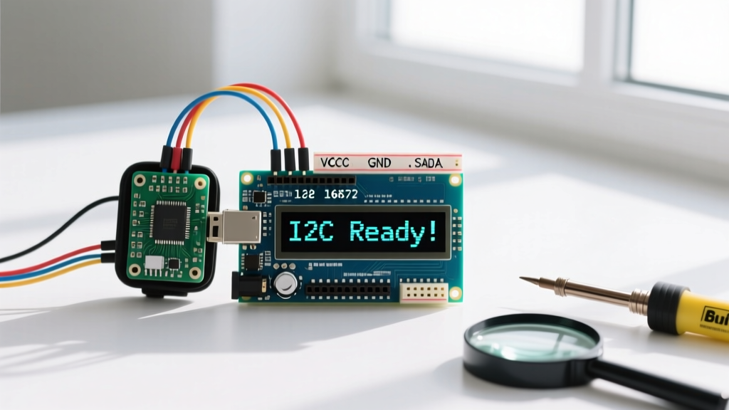
If you are using an ESP32 or Raspberry Pi Pico which lack native segment LCD peripherals, you offload the AC waveform generation to a dedicated driver chip like the NXP PCF8562 or Holtek HT1621. You send standard I2C bytes, and the chip handles the multiplexing and charge pump for the LCD voltage.
- VDD: 3.3V
- VSS: GND
- SDA: GPIO 21 (with 4.7kΩ pull-up)
- SCL: GPIO 22 (with 4.7kΩ pull-up)
- VLCD: Connect a 100nF capacitor to GND (enables the internal charge pump to generate the 3.0V LCD drive voltage).
Decision Tree: Segment LCD vs. Dot-Matrix vs. E-Ink
Choosing the right display technology dictates your entire PCB layout and power budget. Use this decision matrix to select the correct component for your next build.
| Criteria | Custom Segment LCD | Dot-Matrix OLED (SSD1306) | E-Ink / E-Paper |
|---|---|---|---|
| UI Flexibility | Fixed (Hardware etched) | Unlimited (Software pixels) | Unlimited (Software pixels) |
| Active Current Draw | ~15 µA | ~20 mA | ~15 mA (only during refresh) |
| Sunlight Readability | Excellent (Reflective) | Poor (Washes out) | Excellent (Reflective) |
| Refresh Rate | Instant (< 10ms) | Instant (High FPS) | Very Slow (1-2 seconds) |
| NRE / Tooling Cost | High ($500+ for custom glass) | Zero (Off-the-shelf module) | Zero (Off-the-shelf module) |
If your UI requires dynamic menus, scrolling text, or graphs, you must choose a Dot-Matrix OLED or TFT. If your device updates once a day and needs infinite standby time, choose E-Ink. However, if you are building a high-volume, battery-powered sensor node with a fixed UI (like a thermostat, scale, or meter) that requires instant readability in direct sunlight, segment glass is the undisputed winner.
Default Pick: For fixed-UI IoT sensors running on a CR2032 coin cell, specify a custom 4-mux segment LCD driven by an NXP PCF8562 I2C controller. Order the custom glass from a manufacturer like Orient Display or Crystal Clear Tech once your prototype UI is locked.
Frequently Asked Questions
Can I use PWM to dim or adjust the contrast of a segment LCD?
No. Applying PWM to the VCC or logic lines will cause flickering and DC offset degradation. Contrast on a segment LCD is controlled by adjusting the V_LCD drive voltage (the potential difference between the COM and SEG lines). Dedicated driver ICs like the PCF8562 have internal registers to adjust this voltage digitally in millivolt steps.
Why do I need a zebra strip connector instead of soldering?
The ITO layers on the glass are incredibly fragile and cannot withstand the thermal shock of a soldering iron. Zebra strips (elastomeric silicone connectors with alternating conductive and insulative layers) provide reliable, low-resistance electrical contact between the PCB pads and the glass edge using simple mechanical pressure from a bezel or housing.
What happens if my microcontroller crashes and stops toggling the AC waveform?
If the firmware crashes and leaves the GPIO pins in a static HIGH or LOW state, you are applying DC voltage to the liquid crystals. Within a few hours, this will cause irreversible electrochemical plating, resulting in permanent dark stains on the glass. Always implement a hardware watchdog timer to reset the MCU if the display refresh interrupt fails.