A Hall effect sensor detects magnetic flux density and translates it into an electrical signal. The output is strictly one of two types: a ratiometric analog voltage that scales linearly with the magnetic field strength (typically 0.5V to 4.5V), or a digital open-collector logic signal that snaps LOW when a specific magnetic threshold is crossed. You cannot use a digital Hall switch to measure field strength, and you cannot use an analog Hall sensor as a direct logic-level interrupt without software thresholding.
The Physics: How Do Hall Sensors Work?
At the silicon level, a Hall sensor relies on the Lorentz force. When a constant control current flows through a thin semiconductor wafer, applying a perpendicular magnetic field deflects the moving charge carriers (electrons) toward one edge of the wafer. This charge accumulation creates a measurable transverse voltage difference—the Hall voltage—across the material. The strength of this voltage is directly proportional to the perpendicular magnetic flux density passing through the wafer.
Because the raw Hall voltage is only in the microvolt range, practical modules integrate signal conditioning on the same die. Analog sensors (like the A1302 or SS49E) use internal differential amplifiers to boost this microvolt signal into a usable 0-5V ratiometric output centered at VCC/2. Digital sensors (like the A3144) replace the linear amplifier with a comparator and Schmitt trigger, snapping the output transistor to ground only when the magnetic field exceeds a factory-set Gauss threshold, providing built-in hysteresis to prevent chatter.
Analog vs. Digital Outputs: Wiring and Pinouts
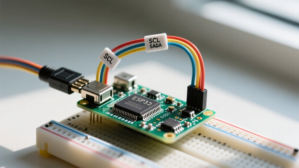
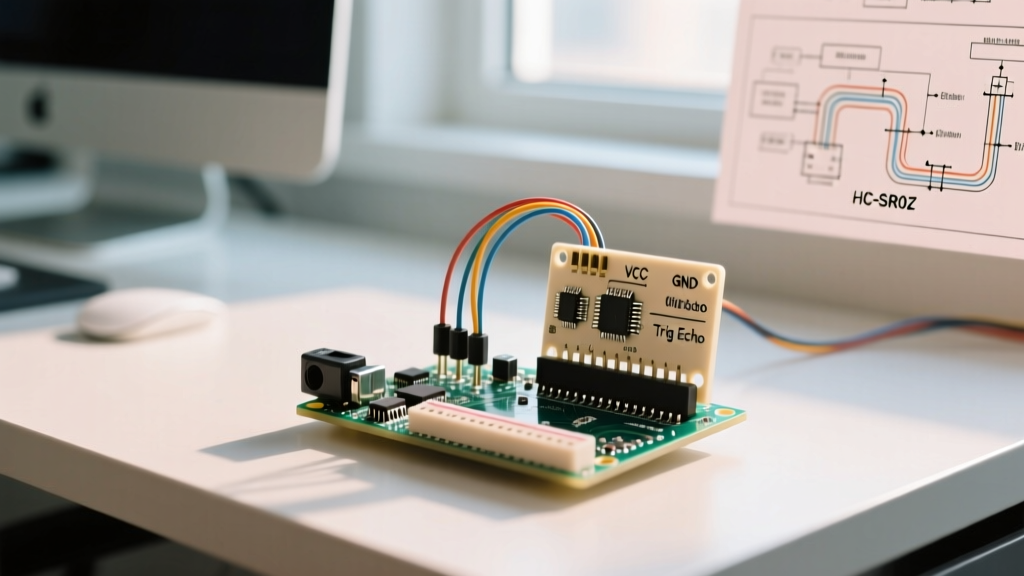
Conflating analog and digital Hall modules is the most common reason a sensor fails to read correctly on a microcontroller. Below is the specification and wiring matrix for the three most common hobbyist and prototyping Hall modules when interfaced with a 3.3V ESP32 DevKit.
| Module / IC | Output Type | VCC Supply Range | Quiescent / Idle State | ESP32 Pin Target | Wiring Notes |
|---|---|---|---|---|---|
| A1302 / SS49E | Analog (Linear) | 2.7V – 5.5V | VCC / 2 (e.g., 2.5V at 5V supply) | GPIO 34 (ADC1_CH6) | If powered at 5V, use a voltage divider (10k/10k) on the signal pin to protect the 3.3V ESP32 ADC. |
| DRV5053 | Analog (Linear) | 2.5V – 3.8V | ~0.25V (Unipolar) or VCC/2 (Bipolar) | GPIO 35 (ADC1_CH7) | Native 3.3V operation. No voltage divider required. Connect VCC directly to ESP32 3V3 pin. |
| A3144 / 49E (Digital) | Digital (Switch) | 3.8V – 24V (A3144) | HIGH (Open-collector, needs pull-up) | GPIO 25 (Digital In) | Requires a 10kΩ pull-up resistor to 3.3V on the signal line. Do not use ADC pins for digital switches. |
Digital Hall switches like the A3144 do not output a HIGH voltage. They only sink current to ground when a magnet is near. You must enable the ESP32 internal pull-up (
INPUT_PULLUP) or use an external 10kΩ resistor to 3.3V, otherwise the pin will float and trigger ghost interrupts.
Output Signal Math: Converting Raw ADC to Gauss
To turn an analog Hall sensor into a functional Gauss meter, you must map the raw ADC reading to a physical magnetic unit. We will use the A1302 powered at a precise 5.0V supply as our worked example. According to the Adafruit Hall Effect guide, the A1302 has a nominal sensitivity of 1.3 mV/Gauss and a quiescent (zero-field) output of VCC/2 (2.5V).
The ESP32’s ADC is notoriously non-linear, especially near the 0V and 3.3V rails. Instead of using the legacy analogRead() which returns a raw 0-4095 integer, modern ESP32 Arduino cores (v2.x and v3.x) provide analogReadMilliVolts(). This function uses the factory-burned eFuse calibration data to return a much more accurate millivolt reading.
The Conversion Formula:
- Read Voltage:
int mV = analogReadMilliVolts(ADC_PIN); - Calculate Delta:
int delta_mV = mV - 2500;(Subtract the 2500mV zero-field quiescent voltage). - Convert to Gauss:
float gauss = delta_mV / 1.3;(Divide by the 1.3 mV/G sensitivity).
Worked Numeric Example:
You place a neodymium magnet near the A1302. The ESP32 reads 1850 from analogReadMilliVolts().
Delta = 1850 mV - 2500 mV = -650 mV.
Gauss = -650 / 1.3 = -500 Gauss (or -50 mT). The negative sign simply indicates the magnetic field polarity (South pole facing the branded side of the sensor).
Interference, Calibration, and Edge Cases
Hall sensors are highly susceptible to environmental noise. If your readings are jittery or drifting, check these three interference sources:
- AC Mains EMI: Routing Hall sensor signal wires parallel to 120V/240V AC lines will induce 50/60Hz noise. The Texas Instruments sensor design guidelines recommend twisting the signal and ground wires and adding a 100nF ceramic bypass capacitor directly across the sensor's VCC and GND pins.
- Brushed Motor Noise: If measuring RPM on a brushed DC motor, the carbon brushes generate broadband RF noise that scrambles analog readings. Use a digital Hall switch (A3144) instead of an analog sensor for RPM counting, as the Schmitt trigger ignores low-amplitude EMI.
- Temperature Drift: The A1302 sensitivity drifts by roughly -0.02% per °C. In a 40°C ambient environment, your 1.3 mV/G sensitivity drops to ~1.25 mV/G. For precision bench work, you must implement software temperature compensation using a co-located thermistor.
Furthermore, always consult the Espressif ESP32 ADC documentation regarding pin selection. Only use ADC1 pins (GPIO 32-39) for Hall sensors. ADC2 pins (GPIO 0, 2, 4, 12-15, 25-27) conflict with the WiFi radio and will drop readings to zero when the ESP32 connects to a network.
Frequently Asked Questions
How do Hall sensors work in brushless DC (BLDC) motors?
In BLDC motors, three digital Hall sensors are embedded in the stator at 60° or 120° electrical offsets. As the rotor's permanent magnets spin past, the sensors output a 3-bit binary sequence (e.g., 101, 100, 110). The motor controller (ESC) reads this sequence to determine the exact rotor position and commutates the stator coils in the correct sequence to maintain rotation. If one sensor fails or a wiring harness breaks, the ESC loses position data and the motor will stutter or fail to start.
How do Hall sensors work with alternating current (AC) wires?
When clamped around an AC wire, a Hall sensor measures the alternating magnetic field generated by the current flow. Because the field reverses direction at 50Hz or 60Hz, an analog Hall sensor will output a sine wave centered around its quiescent voltage. To calculate RMS current, the microcontroller must sample the ADC at a high rate (e.g., 1kHz), find the peak-to-peak voltage swing, convert that to peak Gauss, and divide by the square root of 2. This is the core operating principle of clamp meters and split-core current transformers like the ACS712.
How do Hall sensors work when measuring liquid flow rates?
In liquid flow meters, a small magnet is embedded in the turbine impeller. A digital Hall switch is mounted on the outside of the non-magnetic pipe housing. Every time the impeller completes a rotation, the magnet passes the Hall sensor, pulling the open-collector output LOW. The microcontroller counts these pulses over a specific time window. By knowing the volume of liquid displaced per revolution (the K-factor, usually provided in pulses per liter), the firmware calculates the exact flow rate. Hall sensors are preferred here over reed switches because they do not suffer from mechanical contact bounce or metal fatigue.