
The Hidden Dangers of Direct LED Wiring
Understanding how to wire an LED Arduino setup requires more than just plugging component legs into a breadboard. While a basic blink sketch is the universal rite of passage for makers, treating an LED as a simple plug-and-play load is a primary cause of degraded microcontroller GPIO pins and burnt-out diodes. An LED is a current-driven, non-linear semiconductor device. Without a strict compatibility framework matching your microcontroller's logic level and current sourcing capabilities to the LED's forward voltage ($V_f$) and forward current ($I_f$), you risk catastrophic failure.
This compatibility guide breaks down the exact electrical boundaries of modern microcontrollers, provides precise resistor calculation matrices, and outlines the physical wiring protocols necessary to build robust, long-lasting optoelectronic circuits in 2026.
Microcontroller GPIO Current Limits: The Compatibility Matrix
Before selecting a resistor, you must understand the hard limits of your microcontroller's silicon. Exceeding these limits causes electromigration in the internal bond wires, leading to permanent pin failure. Below is a compatibility matrix for the most common maker boards.
| Microcontroller / Board | Logic Level | Absolute Max Pin Current | Recommended Operating Current | Total GPIO Bank Limit |
|---|---|---|---|---|
| ATmega328P (Uno R3 / Nano) | 5.0V | 40 mA | 20 mA | 200 mA (VCC/GND) |
| ATmega2560 (Mega 2560) | 5.0V | 40 mA | 20 mA | 200 mA (VCC/GND) |
| ESP32-WROOM-32 | 3.3V | 40 mA | 20 mA | 110 mA (Total GPIO) |
| RP2040 (Raspberry Pi Pico) | 3.3V | 12 mA | 4 - 8 mA | 50 mA (Total GPIO) |
Critical Edge Case: The ESP32 features several pins (GPIO 34, 35, 36, and 39) that are input-only. They lack internal pull-up resistors and cannot source current to drive an LED. Always verify your pinout diagram before wiring.
LED Forward Voltage ($V_f$) and Color Chemistry
The semiconductor materials used to create different LED colors dictate their forward voltage drop. You cannot use a single resistor value across all LED colors. According to SparkFun's comprehensive LED physics guide, the bandgap energy of the diode determines both the emitted photon wavelength and the voltage required to turn it on.
| LED Color | Typical $V_f$ (Volts) | Standard $I_f$ (mA) | Required Resistor @ 5V Logic | Required Resistor @ 3.3V Logic |
|---|---|---|---|---|
| Red (Standard) | 2.0V | 20 mA | 150 Ω | 68 Ω |
| Yellow / Green | 2.1V | 20 mA | 150 Ω | 62 Ω |
| Blue | 3.2V | 20 mA | 91 Ω | Not Recommended* |
| White / UV | 3.3V - 3.6V | 20 mA | 82 Ω | Not Recommended* |
*Note on 3.3V Logic Compatibility: Driving a Blue or White LED directly from a 3.3V pin (like the RP2040 or ESP32) is highly problematic. If the LED's actual $V_f$ is 3.4V, a 3.3V logic HIGH will fail to illuminate it. If the $V_f$ is exactly 3.2V, the voltage headroom (0.1V) is too small to calculate a stable current-limiting resistor, leading to thermal runaway. For 3.3V boards, use Red/Yellow/Green LEDs, or use a MOSFET to switch 5V power.
The Math: Calculating the Current-Limiting Resistor
To safely wire an LED to an Arduino, you must apply Ohm's Law to find the correct resistor value. The formula is:
$R = (V_{source} - V_f) / I_f$
Example 1: Wiring a Red LED to an Arduino Uno (5V)
- $V_{source}$: 5.0V
- $V_f$ (Red): 2.0V
- $I_f$ (Target): 20 mA (0.02 A)
- Calculation: (5.0 - 2.0) / 0.02 = 3.0 / 0.02 = 150 Ω
Because 150 Ω is a standard E12 series resistor value, you can use it exactly. A 1/4W carbon film resistor (costing roughly $0.02 each in bulk 2026 pricing) is more than sufficient, as the power dissipation is only $P = I^2R = (0.02)^2 * 150 = 0.06W$.
Example 2: Wiring a Green LED to a Raspberry Pi Pico (3.3V)
- $V_{source}$: 3.3V
- $V_f$ (Green): 2.1V
- $I_f$ (Target): 8 mA (0.008 A) - *Respecting the RP2040's 12mA absolute max and 50mA total bank limit.*
- Calculation: (3.3 - 2.1) / 0.008 = 1.2 / 0.008 = 150 Ω
Physical Wiring Protocol and Polarity
LEDs are polarized diodes; current must flow in only one direction. Reversing the polarity won't immediately destroy the LED, but it will block current flow, and exceeding the reverse breakdown voltage (typically 5V) can cause internal junction failure.
- Identify the Anode (+): The longer leg of the LED. Internally, this connects to the smaller post (the anvil) inside the epoxy lens.
- Identify the Cathode (-): The shorter leg. The plastic lens casing will also have a flattened edge on the side of the cathode. Internally, this connects to the larger post.
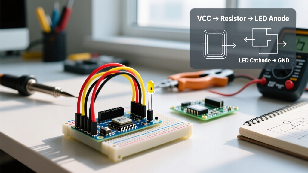
- Resistor Placement: The current-limiting resistor can be placed on either the anode or cathode side. The series circuit limits current equally regardless of component order. However, placing the resistor on the anode (GPIO -> Resistor -> Anode -> Cathode -> GND) is standard practice for easier breadboard troubleshooting.
- Breadboard Tie-Points: Ensure the resistor legs and LED legs are in separate, unconnected tie-point rows. Placing both legs of the resistor in the same row creates a short circuit, bypassing the resistance and sending 5V directly to the LED, instantly vaporizing the internal bond wire.
Advanced Compatibility: Driving High-Power LEDs
Standard 5mm through-hole LEDs max out at roughly 20-30mA. If your project requires high-power illumination (e.g., 1W or 3W Star PCB LEDs drawing 350mA to 700mA), you cannot wire them directly to any microcontroller. Doing so will instantly destroy the GPIO pin and potentially the entire MCU.
For high-current compatibility, you must use a logic-level N-Channel MOSFET as a low-side switch. The ATmega328P datasheet confirms that the 5V output is sufficient to drive logic-level gates, but you must select the correct transistor.
- Use Logic-Level MOSFETs (e.g., IRLZ44N): These have a low Gate Threshold Voltage ($V_{gs(th)}$) and will fully turn on (low $R_{ds(on)}$) at 5V or even 3.3V.
- Avoid Standard MOSFETs (e.g., IRF520): Despite being common in cheap maker kits, the IRF520 requires 10V at the gate to fully saturate. At 5V, it operates in its linear region, acting as a resistor, overheating, and dropping voltage to the LED.
High-Power Wiring Topology
Wire the Arduino GPIO pin to the MOSFET Gate via a 100 Ω gate resistor (to prevent high-frequency ringing). Wire a 10kΩ pull-down resistor from the Gate to Ground to ensure the MOSFET stays off during MCU boot-up sequences when pins are floating. Connect the LED's cathode to the MOSFET Drain, and the MOSFET Source to Ground. Power the LED's anode from an external 5V or 12V power supply capable of sourcing the required amperage.
Troubleshooting Common Wiring Failures
1. The LED is Extremely Dim
Cause: You are likely using a resistor value that is too high (e.g., a 10kΩ resistor instead of 220 Ω), or you are attempting to source current from an input-only pin.
Fix: Verify resistor color bands. Brown-Black-Brown-Gold is 100 Ω. Brown-Black-Orange-Gold is 10k Ω. Check your pinout to ensure you aren't using an ESP32 input-only pin.
2. The Microcontroller Resets Randomly When the LED Turns On
Cause: Brownout. You are powering the Arduino via a weak USB port and driving multiple LEDs simultaneously, causing the board's voltage regulator to drop below the brownout detection threshold (typically 2.7V for the ATmega328P).
Fix: Reduce the current draw by increasing resistor values (e.g., targeting 5mA instead of 20mA per LED) or power the microcontroller via the barrel jack / VIN pin with a regulated 7-9V external supply.
3. The LED Flickers at High PWM Frequencies
Cause: Parasitic capacitance in long breadboard jumper wires combined with high-frequency PWM (Pulse Width Modulation) can cause signal degradation.
Fix: If using PWM for dimming, keep the wires between the GPIO pin and the LED under 15cm. For longer runs, use a twisted-pair cable or buffer the signal with a 74HC125 logic buffer IC.
Summary Checklist for 2026 Maker Projects
Successfully wiring an LED to an Arduino is an exercise in respecting semiconductor physics. Always verify your board's logic level (5V vs 3.3V), calculate the exact resistor requirement using the LED's specific $V_f$, and never exceed the recommended 20mA per pin limit. By treating your GPIO pins as fragile, limited resources rather than infinite power taps, you ensure the longevity of both your microcontroller and your optoelectronic components.