
The Core Concept: How an LED Light Arduino Circuit Works
Connecting an LED to a microcontroller is universally recognized as the 'Hello World' of electronics. However, treating a simple LED light Arduino circuit as a trivial afterthought is the leading cause of burnt-out components and unstable logic levels in beginner and intermediate projects alike. An LED (Light Emitting Diode) is a non-linear semiconductor device. Unlike a simple resistor, it does not obey Ohm's Law linearly; instead, it has a specific forward voltage (Vf) threshold it must overcome before current begins to flow and light is emitted.
When you wire an LED directly to a 5V digital pin on an Arduino Uno R4 Minima (currently retailing around $27.50 in 2026) without a current-limiting resistor, the diode attempts to draw infinite current once the 5V exceeds its Vf. This instantly exceeds the microcontroller's absolute maximum pin rating of 40mA, potentially destroying the ATmega328P or the Renesas RA4M1 silicon inside. To build a robust circuit, you must master the interplay between forward voltage, current limiting, and pulse-width modulation (PWM).
The Physics of the Glow: Forward Voltage and Wavelength
The color of an LED is determined by the semiconductor material's bandgap, which directly dictates its forward voltage. Before calculating your resistor values, you must identify the LED's specific chemistry. Below is a reference matrix for standard 5mm through-hole LEDs commonly used in prototyping.
| LED Color | Typical Forward Voltage (Vf) | Wavelength (nm) | Recommended Test Current |
|---|---|---|---|
| Infrared (IR) | 1.2V - 1.5V | 850 - 940 | 20mA - 50mA |
| Red | 1.8V - 2.2V | 620 - 750 | 20mA |
| Yellow / Green | 2.0V - 2.2V | 570 - 590 | 20mA |
| Pure Green / Blue | 3.0V - 3.4V | 460 - 520 | 20mA |
| White / UV | 3.2V - 3.6V | 380 - 450 | 20mA |
Source: For a deeper dive into semiconductor bandgaps and LED chemistry, refer to the comprehensive SparkFun LED Tutorial.
The Math: Sizing the Current-Limiting Resistor
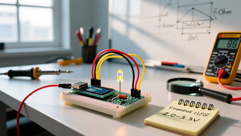
To safely drive an LED, we use a series resistor to drop the excess voltage and limit the current to a safe threshold (usually 20mA for standard indicators). The formula is derived from Kirchhoff's Voltage Law:
R = (V_source - V_f) / I_f
Real-World Example: You are wiring a standard Red LED (Vf = 2.0V) to a 5V digital pin on an Arduino Uno, targeting a safe 15mA (0.015A) current to prolong the LED's lifespan and reduce thermal load on the MCU.
- R = (5.0V - 2.0V) / 0.015A
- R = 3.0V / 0.015A = 200Ω
Since 200Ω is not a standard E12 resistor value, you round up to the nearest standard value: 220Ω. Using a 1/4W carbon film resistor (costing fractions of a cent in bulk) is perfectly adequate here, as the power dissipated by the resistor is only P = I²R = (0.015)² * 220 = 0.0495W.
Sourcing vs. Sinking: Which Configuration to Choose?
Most tutorials teach current sourcing (Pin -> Resistor -> LED -> GND), where the pin outputs HIGH (5V) to turn the LED on. However, current sinking (5V -> Resistor -> LED -> Pin) is often electrically superior. In a sinking configuration, the LED turns on when the pin is driven LOW. Microcontroller pins can typically sink slightly more current than they can source, and sinking avoids potential voltage droop on the VCC rail if multiple LEDs are active simultaneously. For standard indicator LEDs, either is fine, but for multiplexed LED matrices, sinking is the industry standard.
Beyond On/Off: PWM and the analogWrite() Function
If you want to fade your LED light Arduino setup rather than just blink it, you must utilize Pulse Width Modulation (PWM). The analogWrite(pin, value) function simulates an analog voltage by rapidly toggling the digital pin HIGH and LOW. The 'value' ranges from 0 (0% duty cycle / OFF) to 255 (100% duty cycle / FULL BRIGHTNESS).
However, not all PWM pins are created equal. On the classic Arduino Uno architecture:
- Pins 5 and 6: Driven by Timer0, operating at approximately 980 Hz.
- Pins 3, 9, 10, and 11: Driven by Timer1 and Timer2, operating at approximately 490 Hz.
This frequency discrepancy matters if you are combining LED fading with motor control or audio sampling on the same timers. Furthermore, the human eye perceives brightness logarithmically, not linearly. A PWM value of 127 does not look 'half as bright' as 255; it looks nearly identical to the naked eye. To achieve a perceptually smooth fade, you must apply a gamma correction curve in your C++ sketch, mapping linear PWM values to exponential output steps.
Source: Review the official Arduino Fade Example Documentation for baseline implementation code.
Scaling Up: Driving High-Power LED Strips
A standard Arduino digital pin can safely supply a maximum of 20mA (with an absolute, silicon-damaging limit of 40mA). If your project involves high-power illumination, such as a 12V 5050 SMD LED strip drawing 1.5 Amps per meter, connecting it directly to the MCU will instantly vaporize the microcontroller's internal traces.
To bridge the gap between 5V logic and 12V high-current loads, you must use a Logic-Level N-Channel MOSFET (such as the IRLB8721 or STP16NF06L). Unlike older power transistors (e.g., IRF520) which require 10V+ at the gate to fully open, logic-level MOSFETs have a low Gate Threshold Voltage (V_GS(th)), allowing them to switch high currents with just the 5V output from an Arduino pin.
The MOSFET Driver Circuit Checklist
- Gate Resistor (100Ω - 220Ω): Placed between the Arduino pin and the MOSFET gate to limit inrush current caused by the gate's parasitic capacitance.
- Pull-Down Resistor (10kΩ): Placed between the gate and ground. This ensures the MOSFET stays OFF during the Arduino's boot sequence when pins are in a high-impedance (floating) state.
- Flyback Diode (1N4007): Mandatory if you are driving inductive loads (like relays or motors), but generally optional for purely resistive LED strips unless dealing with massive parasitic inductance over long wire runs.
Real-World Failure Modes and Edge Cases
Even with correct math, physical prototypes often exhibit strange behaviors. Here are three common edge cases in LED light Arduino builds and how to solve them:
1. Ghosting and Capacitive Coupling
If you run long wires (over 2 meters) between your Arduino and the LED, you may notice the LED faintly glowing even when the pin is set to LOW. This is caused by parasitic capacitance in the wire acting as an antenna, picking up ambient electromagnetic interference (EMI) or coupling from adjacent PWM wires. Fix: Add a 4.7kΩ pull-down resistor in parallel with the LED to bleed off stray capacitive charge.
2. Thermal Runaway in Resistors
If you are driving multiple parallel LEDs from a single transistor or resistor network, the LEDs will heat up. As an LED's temperature rises, its forward voltage drops. If the voltage drop across the current-limiting resistor remains static, the current will increase, causing more heat—a destructive feedback loop called thermal runaway. Fix: Always use a dedicated resistor for each parallel LED string, rather than one master resistor for the whole parallel bank.
3. Camera Flicker (Beat Frequencies)
When filming your Arduino project for social media or documentation, the LED may appear to strobe or flicker on video, even though it looks solid to the human eye. This occurs when the Arduino's 490Hz PWM frequency clashes with the rolling shutter speed of your smartphone camera. Fix: Use a hardware timer library to push the PWM frequency above 20kHz, moving it entirely out of the visible and camera-detectable spectrum.
Summary: Best Practices for 2026
Building a reliable LED light Arduino circuit goes far beyond plugging a component into a breadboard. By respecting the non-linear physics of the P-N junction, calculating precise current-limiting resistors, applying gamma correction for PWM fading, and utilizing logic-level MOSFETs for high-power strips, you elevate your project from a fragile prototype to a robust, deployment-ready system. Always verify your specific LED's datasheet for exact Vf ratings, and never trust generic bulk-bag specifications blindly.