
The Architecture of the ESP32 Relay X1 Module
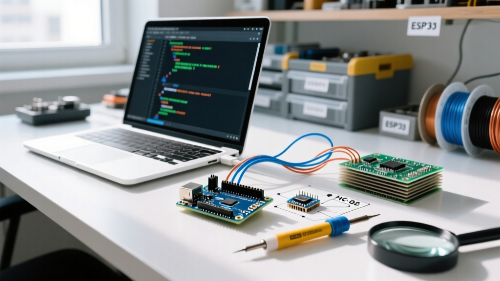
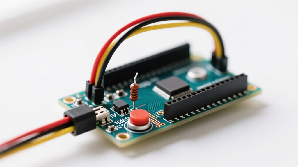
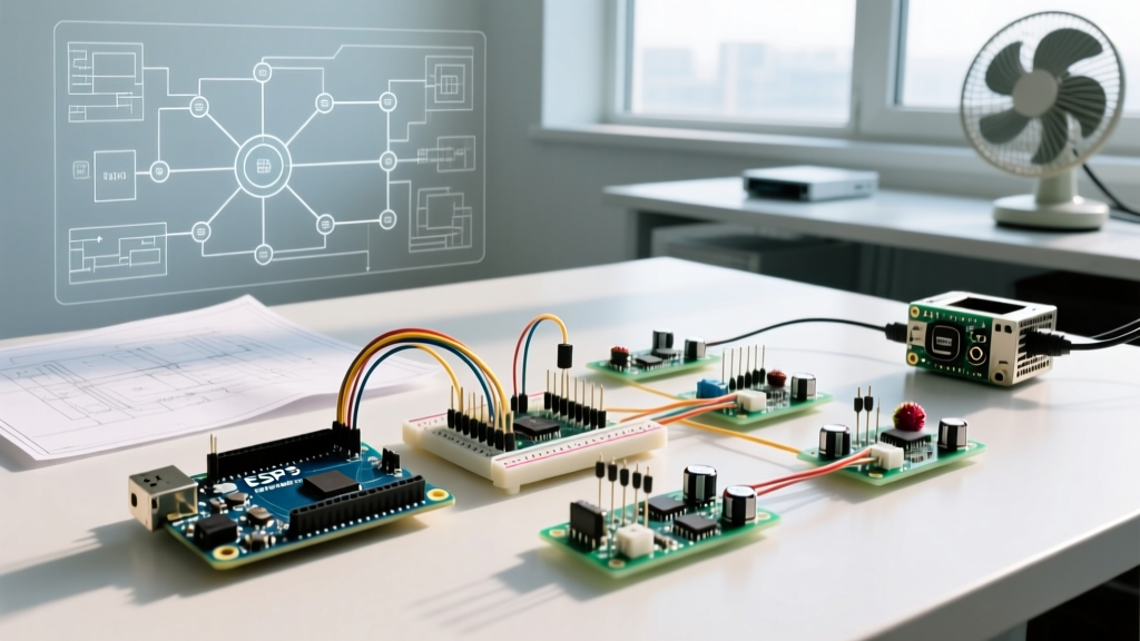
When building IoT smart home devices or industrial automation nodes, the ESP32 Relay X1 configuration represents the foundational building block for high-voltage switching. The 'X1' designation typically refers to the primary single-channel relay node on a schematic or a dedicated 1-channel shield optimized for the ESP32's specific pinout and logic levels. Unlike standard Arduino setups that operate at 5V logic, the ESP32 operates at 3.3V, introducing unique hardware challenges when driving inductive relay coils and optocouplers.
Most generic X1 relay modules utilize the Songle SRD-05VDC-SL-C electromechanical relay. This component features a coil resistance of approximately 70Ω, meaning it draws roughly 71mA of current when energized. While this current is well within the capabilities of a standard 5V power supply, attempting to source this current directly from the ESP32's 3.3V LDO regulator will result in catastrophic voltage sag, triggering the microcontroller's internal brownout detector and causing an endless reboot loop.
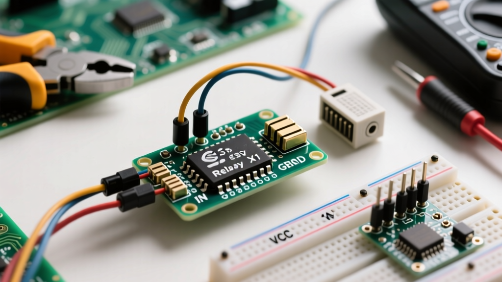
True galvanic isolation is not optional when switching mains voltage. Always verify that your X1 relay module utilizes an optocoupler (like the PC817) and that the JD-VCC jumper is configured correctly to separate the high-voltage switching transient from the ESP32's sensitive 3.3V logic rail.
Hardware Bill of Materials (BOM)
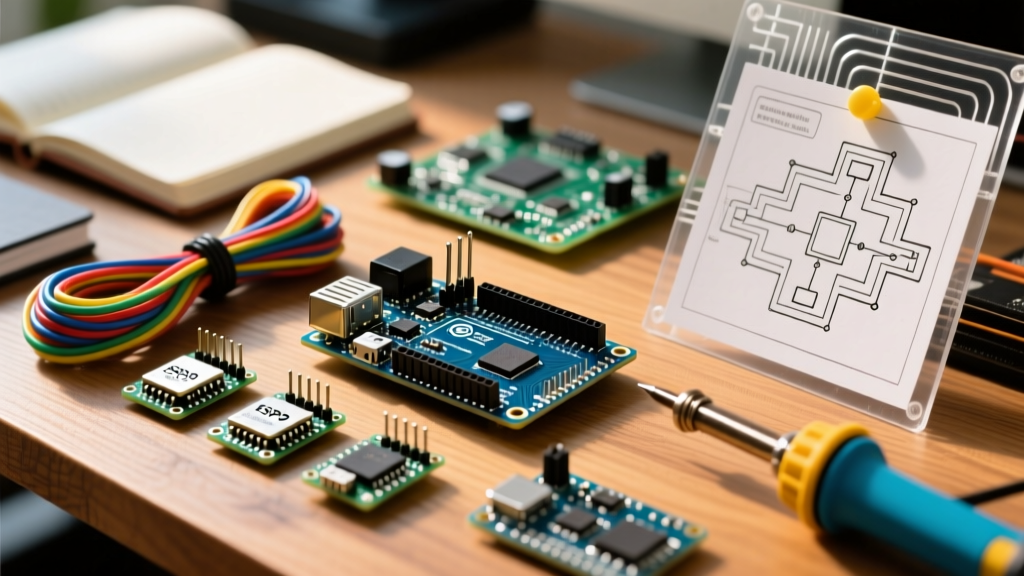
To execute this tutorial safely and reliably, you will need the following components. Do not substitute the ESP32 DevKit V1 with an ESP32-C3 or ESP32-S3 without verifying the specific GPIO boot-strapping requirements, as pin behaviors vary across the SoC family.
| Component | Specification | Purpose & Notes |
|---|---|---|
| Microcontroller | ESP32 DevKit V1 (30-pin) | Dual-core, Wi-Fi/BLE enabled. Avoid ESP32-S2 for this specific pinout. |
| Relay Module | 1-Channel 5V Relay (X1 Config) | Must include PC817 optocoupler and JD-VCC jumper. |
| Power Supply | 5V 2A USB PSU or Buck Converter | Required to handle the 71mA relay inrush plus ESP32 Wi-Fi spikes. |
| Protection | 1N4148 Flyback Diode | Often pre-soldered on the X1 module; verify its presence. |
| Snubber Network | 100Ω 1/2W Resistor + 100nF X2 Cap | For arc suppression across NO/COM contacts on inductive loads. |
Step-by-Step Wiring Guide: Isolation and Mains
The most common point of failure in ESP32 relay projects is improper handling of the logic-level voltage mismatch and the optocoupler's Current Transfer Ratio (CTR). The PC817 optocoupler on the X1 module has an internal LED with a forward voltage of roughly 1.2V. The module typically includes a 1kΩ series resistor. If you drive the IN pin with 3.3V from the ESP32, the current through the LED is calculated as: (3.3V - 1.2V) / 1000Ω = 2.1mA. Because the CTR of a PC817 at low currents can drop below 50%, the phototransistor may not sink enough current to reliably trigger the S8050 driver transistor. This results in a relay that 'chatters' or fails to engage entirely.
Low-Voltage Control Circuit (ESP32 to Relay)
To solve the 3.3V logic issue and ensure true isolation, follow this exact wiring protocol:
- Remove the JD-VCC Jumper: This is the most critical step. The jumper normally connects the relay coil power (5V) to the optocoupler power rail. Removing it breaks the physical copper trace connection between the high-current coil and the logic side.
- Wire JD-VCC to 5V: Connect the JD-VCC pin to your external 5V power supply positive rail.
- Wire VCC to 3.3V: Connect the module's VCC pin to the ESP32's 3.3V output pin. This powers the optocoupler LED side safely.
- Wire GND to GND: Connect the module's GND to the ESP32's GND.
- Signal Pin (IN): Connect the IN pin to GPIO 26 on the ESP32. According to the Espressif GPIO Documentation, GPIO 26 is a safe, general-purpose pin that does not interfere with the internal SPI flash or boot-strapping sequences (unlike GPIO 0, 2, or 12).
High-Voltage Load Circuit (Relay to Appliance)
When wiring the mains AC side to the SRD-05VDC-SL-C screw terminals, always use the Normally Open (NO) and Common (COM) terminals for standard appliances. This ensures that if the ESP32 loses power or crashes, the appliance defaults to the 'OFF' state, which is a fundamental fail-safe requirement in electrical engineering. Strip exactly 8mm of insulation from your 14 AWG or 16 AWG mains wire, tin the ends with solder to prevent stranded wire fraying, and torque the terminal screws firmly to prevent high-resistance hotspots.
C++ Firmware: Non-Blocking Relay Control
Using the delay() function in IoT applications is a critical anti-pattern, as it halts the ESP32's ability to maintain Wi-Fi beacon frames and handle background TCP/IP stack tasks. Below is a production-ready, non-blocking C++ sketch utilizing millis() to toggle the X1 relay safely.
const int RELAY_X1_PIN = 26;
unsigned long previousMillis = 0;
const long interval = 5000; // 5-second toggle interval
bool relayState = false;

void setup() {
  Serial.begin(115200);
  pinMode(RELAY_X1_PIN, OUTPUT);
  // Most X1 modules are Active LOW
  digitalWrite(RELAY_X1_PIN, HIGH);
  Serial.println('ESP32 Relay X1 Initialized');
}

void loop() {
  unsigned long currentMillis = millis();
  if (currentMillis - previousMillis >= interval) {
    previousMillis = currentMillis;
    relayState = !relayState;
    digitalWrite(RELAY_X1_PIN, relayState ? LOW : HIGH);
    Serial.printf('Relay State: %s\n', relayState ? 'ENGAGED' : 'DISENGAGED');
  }
  // Yield to FreeRTOS Wi-Fi tasks
  vTaskDelay(10 / portTICK_PERIOD_MS);
}
For deeper integration with web servers and smart home ecosystems, refer to the comprehensive Random Nerd Tutorials ESP32 Relay Guide, which expands on integrating this exact hardware with ESPAsyncWebServer.
Real-World Troubleshooting: ESP32 Brownouts and Chatter
If you open the Serial Monitor and see the fatal error Brownout detector was triggered, your hardware is failing the inrush current test. When the X1 relay coil energizes, it momentarily draws up to 100mA before settling at 71mA. If you are powering the ESP32 via a standard PC USB port (limited to 500mA) and the AMS1117-3.3 voltage regulator on the DevKit is simultaneously powering the Wi-Fi radio (which spikes to 250mA during transmission), the total current demand exceeds the USB polyfuse threshold or causes the 5V rail to sag below the LDO dropout voltage.
The Solution: Power the ESP32 and the JD-VCC rail using a dedicated 5V 2A (or higher) switching power supply. Connect the 5V PSU directly to the ESP32's VIN pin and the Relay's JD-VCC pin. This bypasses the USB port limitations and provides the necessary transient current headroom.
Advanced Protection: Snubber Circuits and Back-EMF
While the X1 module includes a flyback diode to protect the driver transistor from the relay coil's collapsing magnetic field (Back-EMF), it does nothing to protect the physical relay contacts from arcing when switching inductive loads like HVAC fans, water pumps, or large transformers. When the NO contact opens, the inductive load generates a high-voltage spike that can arc across the physical gap, pitting the contacts and generating severe Electromagnetic Interference (EMI) that can reset the ESP32.
To mitigate this, solder an RC snubber network directly across the NO and COM terminals on the high-voltage side. A series combination of a 100Ω 1/2W carbon composition resistor and a 100nF 275VAC X2-rated capacitor will absorb the inductive spike, extending the mechanical life of the X1 relay from 100,000 cycles to well over 500,000 cycles while keeping the ESP32's RF environment clean.
Safety Protocols for Mains Switching
Working with 120V/240V AC requires strict adherence to safety protocols. Never prototype mains wiring on a breadboard. Always mount the ESP32 and the X1 relay module inside a fire-retardant ABS or polycarbonate DIN-rail enclosure. Maintain a minimum creepage and clearance distance of 8mm between any low-voltage DC traces and high-voltage AC terminals. Use heat-shrink tubing over all exposed AC solder joints, and ensure the enclosure is properly grounded if using a metal chassis. Always verify your wiring with a digital multimeter set to continuity mode before applying mains power to the circuit.