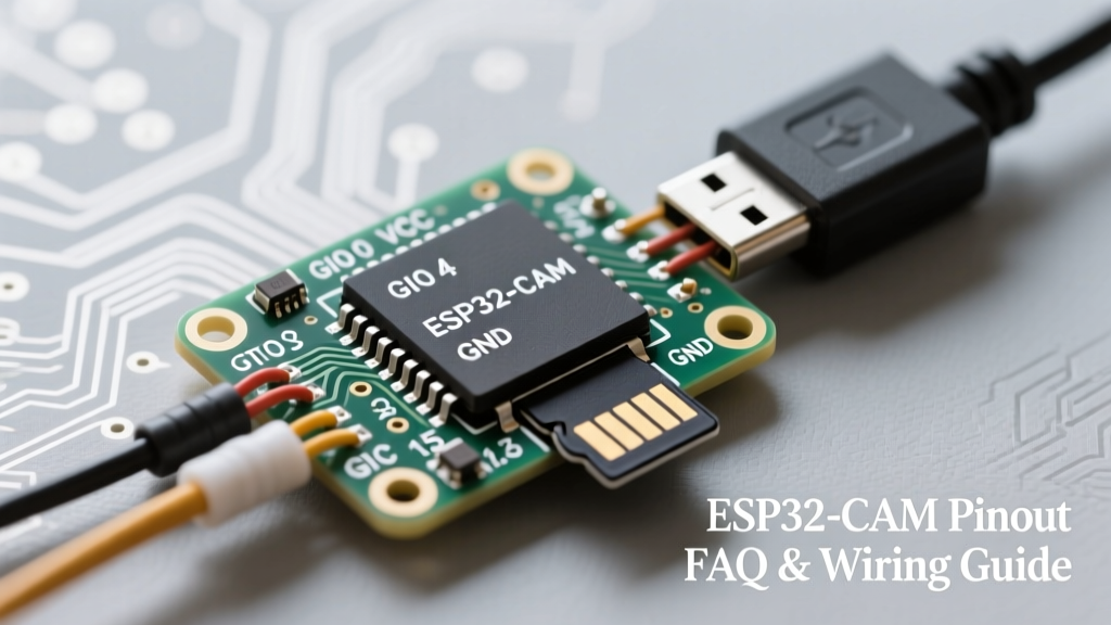

The AI-Thinker ESP32-CAM is arguably the most popular microcontroller module for budget-friendly IoT camera projects. However, its compact footprint comes at a significant cost: a highly restricted and complex GPIO layout. Because the onboard OV2640 camera module and the external PSRAM chip consume the majority of the available pins, understanding the exact ESP32-CAM pinout is critical to avoiding hardware conflicts, boot loops, and brownout resets.
This quick reference guide and FAQ will map out every usable pin, explain the hidden strapping pin constraints, and provide actionable wiring advice for FTDI programmers and peripheral sensors.
Complete ESP32-CAM Pinout Quick Reference Table
Below is the definitive mapping for the standard AI-Thinker ESP32-CAM board. Unlike standard ESP32 DevKits, many of these pins are hardcoded to the camera's DVP (Digital Video Port) interface or the microSD card's SPI bus.
| GPIO | Primary Function | Peripheral Conflict | Boot Constraint |
|---|---|---|---|
| GPIO 0 | Boot Mode Select | Camera XCLK | Must be LOW for flash mode |
| GPIO 2 | SD Card Data / Boot | microSD SPI | Must be LOW or Floating |
| GPIO 4 | Flash LED / SD Data | microSD SPI | None |
| GPIO 12 | SD Card Data / JTAG | microSD SPI | Must be LOW |
| GPIO 13 | SD Card Data / UART | microSD SPI | None |
| GPIO 14 | SD Card Clock | microSD SPI | None |
| GPIO 15 | SD Card Command | microSD SPI | Must be HIGH |
| GPIO 16 | PSRAM Chip Select | None (Reserved) | None |
| GPIO 33 | Internal Red LED | None | None |
Note: GPIOs 5, 18, 19, 21, 22, 23, 25, 26, 27, 32, 34, 35, 36, and 39 are entirely consumed by the OV2640 camera interface and are not exposed on the external header pins.
Critical Strapping Pins & Boot Failures
One of the most common failure modes when wiring external sensors to the ESP32-CAM is accidentally triggering a boot loop. The ESP32 chip relies on specific strapping pins to determine the boot mode and flash voltage during startup. If you wire a pull-down resistor or a sensor that forces a strapping pin into the wrong state, the MCU will fail to execute your sketch.
- GPIO 0: Controls boot mode. Must be
LOWto enter serial bootloader (flashing mode) andHIGH(or floating) for normal SPI flash boot. - GPIO 2: Must be
LOWor floating to boot from SPI flash. If pulled HIGH, the chip attempts to boot from an SDIO peripheral, resulting in a crash. - GPIO 12: Determines the flash operating voltage. Must be
LOWfor 3.3V flash operation. If pulled HIGH, the ESP32 expects a 1.8V flash chip and will brownout. - GPIO 15: Controls boot log output. Must be
HIGHfor normal boot logging.
Expert Troubleshooting Tip: If your ESP32-CAM is stuck in a reboot loop and you have a relay or sensor wired to GPIO 12, disconnect it immediately. Forcing GPIO 12 HIGH changes the internal voltage regulator expectations, leading to catastrophic flash read errors. Always consult the Espressif Strapping Pins Documentation before wiring to these specific GPIOs.
FTDI Programmer Wiring & Power Delivery Constraints
Because the AI-Thinker ESP32-CAM lacks an onboard USB-to-UART bridge, you must use an external FTDI programmer (like the FT232RL) to upload code. However, power delivery is where 90% of makers fail.
The 3.3V vs 5V Brownout Issue
The ESP32-CAM features an onboard AMS1117-3.3 voltage regulator. While the datasheet for the AMS1117 claims an 800mA capacity, the cheap thermal pads and copper pours on clone boards limit safe continuous current to about 400mA. Furthermore, the Wi-Fi radio transmission combined with the camera flash (GPIO 4) can cause transient current spikes up to 480mA.
If you attempt to power the board using the 3.3V pin from a standard FTDI adapter, the adapter's onboard LDO (often a low-quality 3.3V regulator capped at 50mA-200mA) will instantly drop voltage under load. This causes a brownout detector reset, and your serial monitor will spit out endless rst:0xc (SW_CPU_RESET), boot:0x13 errors.
- Correct Wiring: Connect the FTDI
VCCto the ESP32-CAM5Vpin. - Correct Wiring: Connect FTDI
GNDto ESP32-CAMGND. - Correct Wiring: Connect FTDI
TXto ESP32-CAMU0R(GPIO 3). - Correct Wiring: Connect FTDI
RXto ESP32-CAMU0T(GPIO 1). - Flashing Mode: Bridge
GPIO 0toGNDbefore applying power. Remove the bridge and press the onboard RESET button after the upload completes.
For a visual breakdown and code examples, the Random Nerd Tutorials ESP32-CAM Guide remains an excellent supplementary resource for Arduino IDE setup.
ESP32-CAM Pinout FAQ
Why does wiring a sensor to GPIO 16 cause random reboots?
GPIO 16 and GPIO 17 are strictly reserved for the external PSRAM (Pseudo-Static RAM) chip. The AI-Thinker module uses these pins for the PSRAM SPI Chip Select and Clock lines. If you wire a button, relay, or I2C sensor to GPIO 16, the electrical noise or state change will corrupt the PSRAM bus. The moment your sketch attempts to allocate memory for the camera frame buffer in PSRAM, the ESP32 will experience a fatal exception and reboot. Never use GPIO 16 or 17 for general I/O.
Can I use the microSD card and the camera at the same time?
Technically, yes, but practically, it is a massive headache. The camera uses the high-speed DVP interface, while the SD card uses the SPI bus (GPIO 2, 4, 12, 13, 14, 15). Both subsystems require significant memory bandwidth and power. When writing high-resolution JPEGs to the SD card while simultaneously streaming or capturing, the ESP32 often runs out of internal SRAM, forcing it to rely heavily on PSRAM. Furthermore, if you are using the ESP32 Hardware Design Guidelines as a reference, you'll note that sharing SPI buses with high-speed camera data can lead to DMA (Direct Memory Access) conflicts. If you must log data, consider using an external I2C EEPROM or sending the data via Wi-Fi/MQTT instead of the local SD card.
Where is the built-in LED, and how do I control it?
The ESP32-CAM has two LEDs, but neither is wired like a standard Arduino LED_BUILTIN.
1. Flash LED (GPIO 4): This is the high-power white LED used for illumination. Because GPIO 4 is shared with the SD card data line, if you initialize the SD card in your sketch, the flash LED will flicker randomly or fail to turn on.
2. Status LED (GPIO 33): This is a tiny red LED on the back of the board. It is active LOW. To turn it on, set GPIO 33 to LOW. To turn it off, set it to HIGH.
Are there any safe GPIOs left for I2C sensors?
Yes, but your options are severely limited. GPIO 14 and GPIO 15 are the most commonly repurposed pins for I2C (SDA and SCL), provided you do not initialize the microSD card in your code. If the SD card is disabled in the firmware, GPIO 13, 14, and 15 are freed up. GPIO 2 can also be used as an I2C pin, but you must ensure your external circuit does not pull it HIGH during the boot sequence, or the ESP32 will fail to start. Always use external pull-up resistors (4.7kΩ) for I2C, and be mindful of the 3.3V logic level limitations.
Final Thoughts on Hardware Design
Mastering the ESP32-CAM pinout requires accepting its fundamental design compromise: it is a camera module first, and a general-purpose microcontroller second. By respecting the strapping pins, utilizing the 5V input to bypass cheap FTDI voltage regulators, and avoiding the PSRAM SPI bus, you can build highly reliable, low-cost vision systems for your DIY electronics projects.