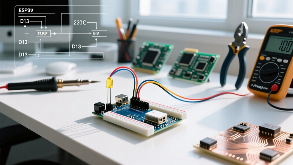

Beyond the Blink: Rethinking the LED Workflow
Most maker tutorials treat the process of wiring an LED as a 30-second afterthought—the ubiquitous 'Hello World' of electronics. However, in professional prototyping and high-volume maker workflows, poor LED wiring practices lead to burnt GPIO pins, inconsistent brightness across arrays, and spaghetti-cable debugging nightmares. Understanding how to connect a led to arduino properly is not just about making a light turn on; it is about establishing a repeatable, scalable, and electrically safe hardware workflow.
This guide discards the basic 'plug it in and guess the resistor' approach. Instead, we will break down the optimized workflow for LED integration, covering precise component math, breadboard hygiene, firmware pin management, and scaling strategies for complex arrays using modern 2026 microcontroller standards like the Arduino Uno R4 Minima and ESP32-C3.
Phase 1: The Pre-Flight Component Matrix
Before touching a breadboard, an optimized workflow demands exact component selection. Grabbing a random 330Ω resistor from a bin might work for a red LED, but it will severely underdrive a blue or white LED, resulting in dim output. Conversely, driving a standard 5mm LED without a current-limiting resistor will pull upwards of 60mA, instantly exceeding the absolute maximum ratings of most microcontroller GPIO pins and causing permanent silicon damage.
According to SparkFun's comprehensive LED physics guide, the forward voltage (Vf) varies significantly by the semiconductor's bandgap (color). Below is the definitive E12-series resistor matrix for standard 5mm through-hole LEDs targeting a safe 20mA forward current (If).
| LED Color | Typical Vf (Volts) | Target If (mA) | 5V Logic Resistor (Uno R3/R4) | 3.3V Logic Resistor (ESP32/Due) |
|---|---|---|---|---|
| Red | 2.0V | 20mA | 150Ω (or 220Ω for safety) | 68Ω |
| Yellow/Green | 2.1V | 20mA | 150Ω | 62Ω |
| Blue | 3.2V | 20mA | 91Ω (or 100Ω) | 10Ω (Use logic-level MOSFET instead) |
| White | 3.4V | 20mA | 82Ω | Do not use direct 3.3V GPIO |
Workflow Note: For 3.3V systems driving Blue or White LEDs, the supply voltage is too close to the LED's forward voltage to reliably regulate current with a simple resistor. The optimized workflow dictates using a logic-level N-channel MOSFET (like the 2N7000) or a dedicated LED driver IC.
Phase 2: Hardware Execution & Breadboard Hygiene
Physical execution is where most prototyping workflows degrade into chaos. To maintain signal integrity and mechanical stability, follow these strict hardware protocols:
1. Polarity Identification
LEDs are diodes; current only flows one way. The anode (positive) is the longer leg, and the cathode (negative) is the shorter leg. If the legs have been clipped, inspect the internal structure of the 5mm epoxy dome: the smaller internal structure (the post) is the anode, while the larger, flat 'anvil' structure is the cathode. Furthermore, the outer plastic rim of the LED base will have a flat edge on the cathode side.
2. Wiring Standards
Abandon floppy, pre-cut stranded Dupont jumper wires for permanent breadboard layouts. They cause intermittent contact resistance and obscure your line of sight. Instead, use 22 AWG solid-core copper wire stripped to exact lengths. A precision wire stripper (such as the Engineer PA-09, typically priced around $28) ensures flush cuts that slide cleanly into breadboard terminals without bending or splaying.
Pro-Tip for Rapid Prototyping: Always route the current-limiting resistor on the anode (high-side) of the LED. While electrically the circuit works either way, placing the resistor on the high-side ensures that if the LED fails short, the resistor still limits current to the microcontroller pin, protecting your silicon.
Phase 3: Firmware Optimization & Pin Management
The hardware is only half the workflow. How you define and manage your pins in the Arduino IDE directly impacts power consumption and debugging efficiency. As detailed in the official Arduino Digital Pins documentation, microcontroller pins default to high-impedance inputs upon boot.
Type-Safe Pin Definitions
Stop using #define LED_PIN 13. The C++ preprocessor simply does a blind text replacement, which can lead to maddening type-mismatch bugs in complex sketches. Instead, use constant integers:
const uint8_t LED_PIN = 13;
This enforces type safety, consumes zero dynamic SRAM (the compiler optimizes it into flash memory), and allows the IDE's autocomplete to recognize your variables.
Preventing Ghosting and Leakage
You must explicitly declare pinMode(LED_PIN, OUTPUT); in your setup() function. If you attempt to write HIGH to a pin configured as an INPUT, you are merely enabling the internal 20kΩ-50kΩ pull-up resistor. This will result in a 'ghosting' effect where the LED glows faintly, drawing roughly 150µA, which is disastrous for battery-powered IoT nodes.
Phase 4: Scaling the Workflow (Beyond 5 LEDs)
If your project requires more than five LEDs, stop wiring them directly to the Arduino's GPIO pins. The ATmega328P (Uno R3) and Renesas RA4M1 (Uno R4) have strict per-pin (20mA recommended) and total-package current limits. Exceeding the total VCC/GND package limit (typically 200mA for the ATmega328P) will cause the microcontroller to overheat and enter thermal shutdown or fail catastrophically.
The Shift Register Solution
For 8 to 64 LEDs, the industry-standard workflow optimization is the 74HC595 8-bit shift register. Costing roughly $0.45 per unit in bulk, it allows you to control 8 independent LEDs using only 3 Arduino GPIO pins (Data, Clock, Latch). By daisy-chaining the QH' (serial out) pin to the next chip's data input, you can scale to dozens of LEDs while maintaining precise software control via the shiftOut() function.
For high-density matrices (e.g., 8x8 LED grids), bypass shift registers entirely and utilize a dedicated I2C/SPI LED driver like the MAX7219. It handles all multiplexing and current regulation in hardware, freeing your microcontroller to focus on application logic rather than display refreshing.
Debugging Edge Cases & Failure Modes
When the LED fails to illuminate, do not immediately rewrite your code. Follow this systematic hardware-debugging workflow:
- The Multimeter Diode Test: Set your digital multimeter to the diode test mode (usually indicated by a diode symbol). This mode applies roughly 2V at 1mA. Touch the red probe to the anode and black to the cathode. A functioning LED will light up dimly and display its forward voltage (e.g., '1.850' for red). If it reads 'OL' (Open Loop), the LED is dead or wired backward.
- Floating Pin Verification: Use the multimeter's DC voltage mode to probe the GPIO pin relative to ground while the sketch is running. If you see 5V (or 3.3V) but the LED is dark, your resistor is open or the LED cathode lacks a ground path.
- Reverse Polarity Damage: Standard 5mm LEDs have a reverse breakdown voltage of roughly 5V. If you accidentally connect a red LED directly across 5V and GND backward, it may survive. However, if you are driving LEDs from a 12V external supply using a transistor, a reverse polarity fault will instantly shatter the LED's internal semiconductor junction.
Conclusion
Mastering how to connect a LED to Arduino is the foundational benchmark of a disciplined maker. By shifting from trial-and-error wiring to a calculated workflow—utilizing exact E12 resistor values, enforcing high-side current limiting, practicing strict breadboard hygiene, and knowing exactly when to offload to a 74HC595 shift register—you eliminate hardware variables. This ensures that when your code compiles and uploads, the physical circuit behaves exactly as engineered, saving hours of frustrating troubleshooting.