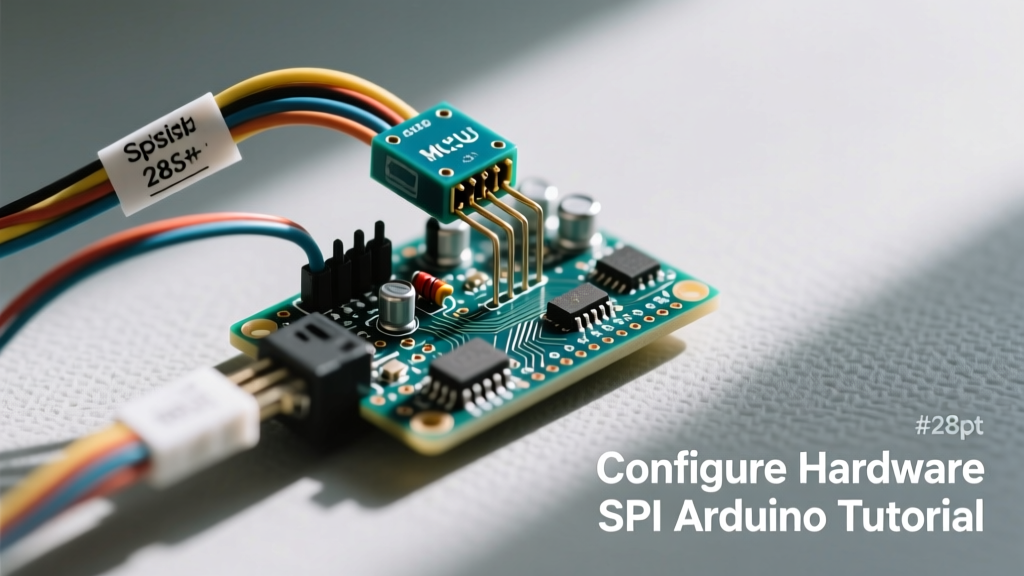

The Architecture of Hardware SPI vs. Bit-Banging
When designing embedded systems, the method you choose to move data between a microcontroller and a peripheral dictates your CPU overhead and maximum throughput. Hardware SPI (Serial Peripheral Interface) utilizes dedicated shift registers and clock generators built directly into the microcontroller's silicon. Unlike Software SPI (often called bit-banging), which relies on the CPU to manually toggle GPIO pins high and low via shiftOut() functions, hardware SPI offloads the timing to a dedicated peripheral module. This allows the ATmega328P or SAMD21 to process other tasks—or enter low-power sleep modes—while bytes are transmitted in the background via Direct Memory Access (DMA) or hardware interrupts.
According to the Arduino SPI Reference, utilizing the native hardware bus is mandatory when interfacing with high-speed peripherals like TFT LCD displays, external SPI Flash memory (e.g., W25Q128), or high-sample-rate ADCs, where software bit-banging would introduce severe latency and screen tearing.
Mapping the Pins: ATmega328P and SAMD21 Defaults
One of the most common pitfalls for makers transitioning between Arduino architectures is assuming SPI pins are universally mapped to pins 11, 12, and 13. While true for the classic Uno, modern ARM-based boards route hardware SPI differently to accommodate advanced pin multiplexing.
| Board Architecture | Microcontroller | MOSI (COPI) | MISO (CIPO) | SCK (SCLK) | SS (CS) |
|---|---|---|---|---|---|
| Arduino Uno / Nano | ATmega328P (AVR) | Pin 11 | Pin 12 | Pin 13 | Pin 10 |
| Arduino Mega 2560 | ATmega2560 (AVR) | Pin 51 | Pin 50 | Pin 52 | Pin 53 |
| Arduino Zero / MKR | SAMD21 (ARM Cortex-M0) | ICSP Header / Pin 23 | ICSP Header / Pin 22 | ICSP Header / Pin 24 | Variable (Software defined) |
| ESP32 DevKit V1 | Xtensa LX6 (Dual Core) | GPIO 23 (VSPI) | GPIO 19 (VSPI) | GPIO 18 (VSPI) | GPIO 5 (VSPI) |
Pro-Tip for Custom PCB Design: When routing an ATmega328P for a custom board, always break out the 2x3 ICSP header. The ICSP header guarantees access to the hardware SPI bus regardless of how the digital pins are remapped in future board revisions.
Understanding SPI Modes and Clock Polarity
Before initializing the bus, you must understand the clock phase (CPHA) and clock polarity (CPOL) required by your target peripheral. As detailed in SparkFun's comprehensive SPI tutorial, these two parameters define the four standard SPI Modes:
- Mode 0 (CPOL=0, CPHA=0): Clock is idle LOW. Data is sampled on the rising edge. (Most common for SD cards and SPI Flash).
- Mode 1 (CPOL=0, CPHA=1): Clock is idle LOW. Data is sampled on the falling edge.
- Mode 2 (CPOL=1, CPHA=0): Clock is idle HIGH. Data is sampled on the falling edge.
- Mode 3 (CPOL=1, CPHA=1): Clock is idle HIGH. Data is sampled on the rising edge. (Common for certain accelerometers like the ADXL345).
Using the wrong mode will result in shifted bits, where the master reads the previous byte's trailing bit or completely corrupted data registers.
Step-by-Step: Initializing the SPI Bus in C++
Modern Arduino development relies on the SPISettings object to configure the bus safely, especially in environments where multiple SPI devices share the same MISO/MOSI lines but require different clock speeds.
#include <SPI.h>

// Define the Chip Select pin for your peripheral
const int CS_PIN = 10;

void setup() {
  // Initialize the hardware SPI bus
  SPI.begin();

  // Configure the Chip Select pin as OUTPUT
  pinMode(CS_PIN, OUTPUT);
  digitalWrite(CS_PIN, HIGH); // Deselect the chip (Active LOW)
}

void loop() {
  // Begin a transaction tailored to a specific peripheral
  // Parameters: Speed (Hz), Bit Order, SPI Mode
  SPI.beginTransaction(SPISettings(8000000, MSBFIRST, SPI_MODE0));

  digitalWrite(CS_PIN, LOW); // Assert Chip Select

  // Transfer data (simultaneously sends and receives)
  byte response = SPI.transfer(0x9F); // Example: Read JEDEC ID
  byte manufacturer = SPI.transfer(0x00);

  digitalWrite(CS_PIN, HIGH); // Deassert Chip Select

  // End the transaction to release the bus for other devices
  SPI.endTransaction();

  delay(1000);
}
Calculating Clock Dividers and Maximum Speeds
On a 16MHz ATmega328P, the absolute maximum hardware SPI clock speed is F_CPU / 2, which equals 8MHz. If you request 10MHz via SPISettings, the Arduino core will automatically round down to the nearest supported hardware divider (8MHz). Legacy code often uses SPI.setClockDivider(SPI_CLOCK_DIV2), but this is deprecated in favor of SPISettings because the latter ensures interrupt safety and prevents bus collisions when multiple libraries attempt to alter the global SPI registers simultaneously.
Hardware Design: Logic Level Shifting for 3.3V Peripherals
A critical failure mode in maker projects involves connecting 5V Arduino SPI pins directly to 3.3V peripherals like the W25Q128 Flash chip or nRF24L01+ radio modules. The ATmega328P outputs 5V on its MOSI and SCK lines. Feeding 5V into a 3.3V CMOS input can cause immediate gate oxide breakdown or long-term thermal degradation.
To safely interface 5V hardware SPI with 3.3V devices, you must implement a level shifter. While resistor dividers work for low-speed I2C or UART, they are unsuitable for SPI due to the RC low-pass filter effect created by the parasitic capacitance of the traces and the resistor network, which rounds off the sharp square waves required for high-speed clock edges.
Recommended Level Shifters for SPI:
- 74AHCT125: A quad buffer with 5V-tolerant inputs that outputs clean 3.3V signals when powered at 3.3V. Ideal for MOSI and SCK.
- BSS138 MOSFETs: The standard bi-directional level shifting circuit used on Adafruit and SparkFun breakout boards. Excellent for MISO, as it allows the 3.3V slave to pull the line low safely without back-feeding 5V into the master.
- SN74LVC1T45: Texas Instruments single-bit dual-supply transceivers offering edge rates capable of supporting SPI clocks well over 20MHz.
Troubleshooting Signal Integrity and MISO/MOSI Swaps
When your hardware SPI bus returns 0xFF or 0x00 continuously, the issue is rarely the code. It is almost always a physical layer fault. According to analog engineers at Analog Devices, SPI buses are highly susceptible to capacitive loading and ground bounce.
1. The Floating Chip Select (CS) Problem
If you have multiple SPI devices on the same bus, a device that is currently unselected (CS HIGH) must have its MISO pin in a high-impedance (Hi-Z) state. If a peripheral lacks internal Hi-Z logic on its MISO pin, it will clash with the active device. Always verify your peripheral's datasheet. If Hi-Z is not guaranteed, add a 74LVC1G125 tri-state buffer on the MISO line of each slave, gated by the local CS pin.
2. Trace Length and Ringing
At 8MHz, the rise and fall times of the SPI clock are incredibly fast (often under 5 nanoseconds). If your jumper wires or PCB traces exceed 15-20 centimeters, the inductance of the wire combined with parasitic capacitance will cause signal ringing. This ringing can cross the logic threshold voltage multiple times per edge, causing the slave microcontroller to register multiple clock pulses for a single master tick. Solution: Keep SPI traces under 10cm, route them over a continuous ground plane, and add 33-ohm series termination resistors on the MOSI and SCK lines near the master to dampen reflections.
3. Ground Loops and Common-Mode Noise
When communicating with SPI devices located on separate boards or in noisy environments (like near stepper motor drivers), the ground potential between the master and slave can fluctuate. This causes the master's logic HIGH to be misinterpreted by the slave. Always ensure a heavy gauge ground wire connects the master and slave directly, alongside the SPI ribbon cable, to minimize the ground return path impedance.