
The Voltage Divide: 5V vs 3.3V Logic Levels
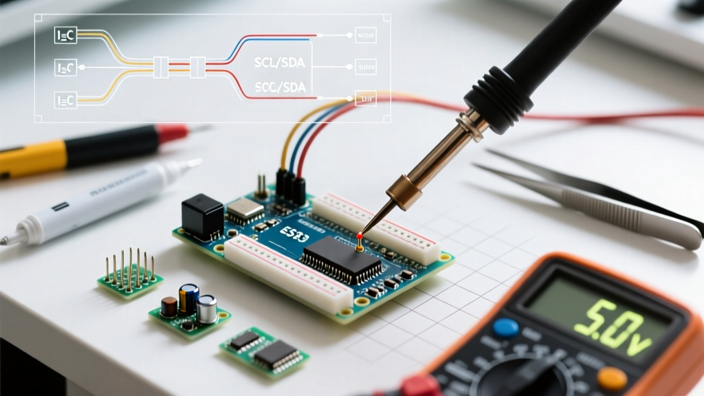
When integrating an arduino screen into your build, the most catastrophic mistake you can make is ignoring logic voltage thresholds. The classic Arduino Uno R3 and Mega 2560 operate at 5V logic. However, the vast majority of modern, high-resolution displays—especially IPS TFTs and high-density OLEDs—are strictly 3.3V tolerant. Feeding 5V from an ATmega328P's SPI or I2C pins directly into the data lines of an ILI9341 or SSD1306 display will degrade the silicon over time or instantly fry the controller IC.
If you are pairing a 5V board with a 3.3V display, you must implement bidirectional logic level shifting. While resistor voltage dividers work for slow, unidirectional signals like SPI MOSI or CLK, they fail miserably on bidirectional I2C lines due to capacitance issues that destroy signal rise times. Instead, use a dedicated MOSFET-based level shifter like the BSS138 or a hex buffer IC like the CD4050B. For a comprehensive breakdown of voltage thresholds, refer to the SparkFun Logic Levels Tutorial.
Protocol Bottlenecks: I2C vs. SPI vs. Parallel
The communication protocol dictates both your wiring complexity and your maximum refresh rate. Choosing the wrong interface for your specific screen type will result in sluggish UI updates or outright failure to initialize.
- I2C (Inter-Integrated Circuit): Ideal for small monochrome OLEDs (like the 0.96-inch 128x64 SSD1306). It requires only two data pins (SDA, SCL) but is bottlenecked by its 400kHz Fast Mode ceiling. Do not use I2C for color screens larger than 1.3 inches; the frame refresh rate will be visibly laggy.
- SPI (Serial Peripheral Interface): The gold standard for color TFTs and e-paper displays. Operating at 8MHz to 40MHz, SPI pushes pixel data fast enough for basic animations. However, it consumes 5 to 6 digital pins (MOSI, MISO, SCK, CS, DC, RST), which can cause pin-starvation on smaller boards like the Nano.
- 8-Bit Parallel: Reserved for massive 3.5-inch to 7-inch screens (e.g., ILI9488 drivers). It requires 8 data pins plus control lines, making it incompatible with standard Unos but perfect for the Mega 2560 or Arduino Due.
The SRAM Ceiling: Framebuffers and Microcontroller Memory
Memory constraints are the silent killer of display projects. To draw graphics, libraries typically allocate a 'framebuffer' in the microcontroller's SRAM—a 1:1 map of the screen's pixels. Let's look at the math for a standard 2.4-inch 320x240 16-bit color TFT screen:
320 pixels × 240 pixels × 2 bytes (16-bit color) = 153,600 bytes (150 KB) of SRAM.
The ATmega328P on the Arduino Uno has a mere 2 KB of SRAM. The Mega 2560 has 8 KB. Neither can hold a full framebuffer for a standard color TFT. If you attempt to initialize a standard Adafruit GFX buffer on an Uno, the sketch will compile, but the MCU will instantly crash and reboot upon execution due to stack collision. For 8-bit and 32-bit AVRs, you must use 'direct-draw' libraries that push pixels to the screen sequentially without caching the whole frame, or upgrade to an ARM-based board like the Arduino Portenta or ESP32, which boasts 520 KB of SRAM. Read more about MCU memory architectures in the Official Arduino Memory Guide.
The Master Arduino Screen Compatibility Matrix
Use this reference table to match your development board with the correct display technology, native voltage, and driver IC.
| MCU Board | Native Logic | Recommended Screen Tech | Safe Interface | Target Driver IC |
|---|---|---|---|---|
| Uno R3 / Nano | 5V | Monochrome OLED (0.96") | I2C (w/ Level Shifter) | SSD1306 / SH1106 |
| Mega 2560 | 5V | 3.5" Color TFT | 8-Bit Parallel | ILI9488 / HX8357D |
| Nano 33 IoT | 3.3V | 1.3" IPS Color LCD | SPI (Direct Connect) | ST7789 |
| ESP32 DevKit | 3.3V | 2.9" E-Paper / E-Ink | SPI (Direct Connect) | UC8151D / SSD1680 |
| Arduino Due | 3.3V | 5.0" Capacitive Touch | SPI / Parallel | RA8875 |
Navigating the Library Ecosystem
Hardware compatibility is only half the battle; software support dictates your development speed. The Adafruit GFX Library remains the industry standard for basic shapes, text, and bitmaps, acting as a universal translator between your code and the display driver. However, GFX is heavily reliant on framebuffers.
For memory-constrained boards driving complex TFTs, TFT_eSPI by Bodmer is vastly superior. It bypasses the Arduino SPI API and writes directly to the hardware SPI registers of the ESP32 or ATmega, achieving frame rates up to 400% faster than standard libraries. For monochrome OLEDs and e-paper displays, U8g2 is the undisputed champion, offering a 'page buffer' mode that chops the screen into horizontal slices, allowing you to drive a 256x64 OLED using less than 300 bytes of SRAM.
Pro-Tip on E-Paper Displays: Never use standard SPI pinouts for E-Ink screens without checking the 'Busy' pin. E-paper displays take 2 to 15 seconds to refresh. If your MCU attempts to send new data before the screen clears its internal latch, the display will freeze in a corrupted state. Always wire the BUSY pin and poll it in your loop.
Real-World Failure Modes & Troubleshooting
Even with perfect compatibility on paper, makers frequently encounter the 'White Screen of Death' or a completely black, unresponsive display. Here is how to diagnose the most common hardware-level failures:
- The Backlight Pin Oversight: Many SPI TFT modules have a dedicated LED or BLK pin. If this is not tied to 3.3V/5V (or driven HIGH via a GPIO), the screen is rendering your graphics perfectly, but the backlight is off, making it look dead.
- I2C Address Collisions: If you are daisy-chaining an OLED with an I2C sensor (like a BME280), they often share the default 0x3C or 0x76 addresses. Use an I2C Scanner sketch to verify addresses, and look for screens with a physical solder jumper on the back to shift the address to 0x3D.
- Reset Pin Timing: Displays like the ST7789 require a very specific hardware reset sequence on boot. If your MCU's RST pin is tied to the display's RST pin, the display might reset *after* the MCU has already sent the initialization SPI commands. Always use a dedicated GPIO for the display reset and trigger a 150ms LOW pulse in your
setup()function before callingtft.init().
By respecting logic thresholds, calculating your SRAM overhead, and matching the correct driver IC to your chosen library, you can eliminate 95% of display integration headaches and build robust, responsive interfaces for any maker project.