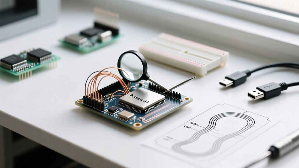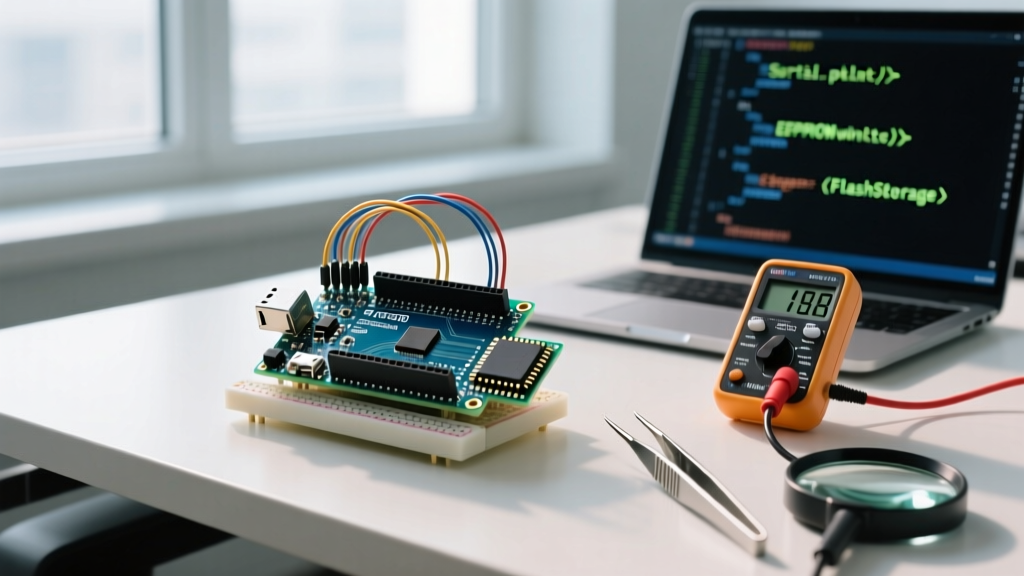

The Limits of Serial Debugging in Production
For hobbyists and rapid prototyping, Serial.println() is the undisputed king of debugging. However, when transitioning a project from the workbench to a deployed, standalone environment, tethered serial monitoring becomes impossible. More critically, standard serial output is volatile; if your microcontroller experiences a brownout, a watchdog reset, or a hard fault, the moments leading up to the crash are lost forever. Upgrading your arduino error logging architecture from volatile serial streams to persistent, non-volatile storage is a mandatory migration step for any production-grade IoT or industrial device.
This migration guide outlines the exact hardware pathways, software architectures, and edge-case handling required to build a resilient logging system that survives power cycles and captures fatal crashes.
Hardware Migration Matrix: Where to Store Logs
The first step in upgrading your logging infrastructure is selecting the right non-volatile memory. Relying on the internal EEPROM of an ATmega328P is a common beginner mistake; it offers a mere 1KB of space and a limited 100,000 write-cycle lifespan, which a verbose logger will exhaust in days. Below is a comparison of viable storage mediums for modern deployments.
| Storage Medium | Typical IC / Module | Capacity | Endurance (Write Cycles) | Est. Cost (2026) | Best Use Case |
|---|---|---|---|---|---|
| Internal EEPROM | ATmega328P Internal | 1 KB | ~100,000 | $0 (On-chip) | Storing single boot counters or fatal error codes. |
| External I2C EEPROM | AT24C256 (Microchip) | 32 KB | ~1,000,000 | $1.20 - $1.80 | Low-frequency event logging, configuration backups. |
| SPI NOR Flash | W25Q32 (Winbond) | 4 MB | ~100,000 per sector | $0.60 - $0.90 | High-frequency logging, OTA firmware, LittleFS integration. |
| MicroSD Card | Generic Class 10 Adapter | 8 GB+ | Controller-managed | $2.50 - $4.00 | Massive CSV data logging, user-retrievable diagnostics. |
The Brownout Failure Mode: Why SD Cards Fail in the Field
While MicroSD cards seem like the obvious choice due to their massive capacity, they introduce a severe vulnerability: FAT32 corruption during power loss. If your Arduino loses power while the SD controller is updating the File Allocation Table, the entire filesystem can become unreadable. For mission-critical error logging, the industry standard has shifted toward SPI NOR Flash chips (like the W25Q32) formatted with wear-leveling filesystems like LittleFS, which are designed to recover gracefully from interrupted writes.
Step-by-Step Software Architecture Upgrade
Moving to flash memory requires a shift in how you handle write operations. Flash memory must be erased in large blocks (sectors) before writing, and excessive writes will destroy the chip. You cannot simply replace Serial.print() with file.print().
Step 1: Implement an SRAM Ring Buffer
To minimize write cycles and prevent blocking your main loop, implement a ring buffer in the microcontroller's SRAM. Logs are written to this buffer instantly. Only when the buffer reaches a defined threshold (e.g., 256 bytes) or a critical error occurs is the data flushed to the external flash.
- Buffer Size: 256 to 512 bytes (easily fits in the 8KB SRAM of an RP2040 or the 520KB SRAM of an ESP32-S3).
- Flush Trigger 1: Buffer reaches 80% capacity.
- Flush Trigger 2: A severity level of
FATALorERRORis logged. - Flush Trigger 3: A periodic timer expires (e.g., every 5 seconds).
Step 2: Transition to LittleFS on SPI Flash
For ESP32 and RP2040 ecosystems, LittleFS is the premier choice for flash logging. Unlike FAT32, LittleFS uses a wear-leveling algorithm that distributes writes evenly across the flash chip, extending the life of a $0.80 W25Q32 chip to years of continuous logging. Furthermore, LittleFS guarantees power-loss resilience. If a write is interrupted, the filesystem rolls back to the previous valid state without corrupting the entire directory structure.
Expert Tip: When configuring LittleFS on an ESP32-S3, allocate a dedicated partition for logs separate from your OTA firmware partitions. A 1MB partition formatted as LittleFS provides ample space for rolling log files while keeping your firmware update process isolated and safe.
Capturing Fatal Crashes and Watchdog Resets
The true test of an arduino error logging system is its ability to explain why the device rebooted. Standard logging fails here because the crash destroys the SRAM buffer before it can be flushed to flash.
ESP32 Core Dump to Flash
If you are migrating from an 8-bit AVR to a 32-bit ESP32, you gain access to hardware-level crash reporting. The ESP-IDF framework includes a Core Dump feature that automatically captures the CPU state, registers, and active task stacks at the exact moment of a panic or unhandled exception. By configuring the ESP32 to save the core dump to a dedicated flash partition, your device can reboot, read the dump on startup, and transmit the exact line of code that caused the fault to your cloud backend.
AVR Watchdog and MCUSR Tracking
For legacy 8-bit boards like the Arduino Uno or Nano (ATmega328P), you must manually track reset vectors. Upon boot, before the bootloader clears it, read the MCUSR (Microcontroller Unit Status Register). This register tells you if the reboot was caused by a power-on event, an external reset pin, a brownout detector (BOD), or the Watchdog Timer (WDT).
By writing a custom bootloader hook or using the optiboot watchdog features, you can capture the MCUSR value, write it to the first byte of the internal EEPROM, and then append it to your external I2C EEPROM log upon initialization. This ensures you always know if a field device is stuck in a brownout reboot loop.
Migration Checklist for Field Deployment
Before deploying your upgraded logging architecture, verify the following parameters to ensure long-term reliability:
- Rolling File Management: Implement a log rotation strategy. Configure your logger to create a new file (e.g.,
log_01.txt) when the current file hits 100KB, and overwrite the oldest file when storage reaches 90% capacity. - Timestamp Synchronization: If your MCU lacks a Real-Time Clock (RTC), log uptime in milliseconds (
millis()) alongside a UNIX epoch timestamp fetched via NTP upon boot. This allows backend parsers to reconstruct accurate timelines even if the device loses network connectivity. - Log Levels: Implement compile-time macros to strip
DEBUGandTRACElogs from production firmware, saving both flash space and CPU cycles. - Brownout Detection (BOD): Ensure the hardware BOD is enabled (e.g., set to 2.7V for 5V AVR boards). Writing to flash or EEPROM during a voltage droop can corrupt memory; a properly configured BOD will halt the CPU before a corrupted write occurs.
Upgrading your logging infrastructure requires upfront engineering effort, but transitioning from volatile serial prints to structured, non-volatile flash storage transforms an unpredictable prototype into a maintainable, professional-grade product.