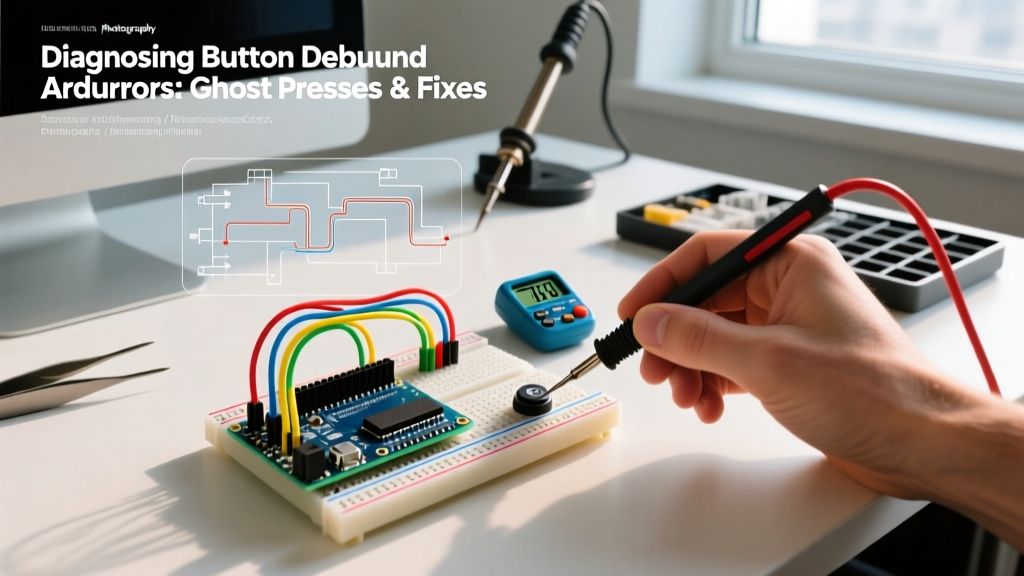

The Prototyping Bottleneck: Moving Beyond the Basic Arduino Button LED
Every maker’s journey begins with the same foundational circuit: the Arduino button LED toggle. While the standard tutorial—reading a digital pin, toggling a boolean, and deploying a 50-millisecond delay() to handle switch bounce—works for a blinking light, it creates a massive workflow bottleneck when scaling to complex projects. In 2026, with microcontrollers like the Arduino Uno R4 Minima ($27.50) and Nano Every ($11.50) offering immense processing power, relying on blocking delays is an architectural anti-pattern.
Optimizing your workflow means treating the humble button and LED not as isolated components, but as an integrated human-machine interface (HMI) system. This requires a paradigm shift in hardware selection, circuit topology, and non-blocking software design. By implementing robust state machines and understanding the physics of contact bounce, you can eliminate ghost inputs, reduce debugging time, and build scalable firmware.
Hardware Selection: The Physics of Contact Bounce
The most common failure mode in beginner button circuits isn't software; it's cheap hardware. Generic, unbranded 6x6mm tactile switches often exhibit contact bounce lasting anywhere from 5ms to 15ms. When the mechanical contacts collide, they physically rebound, creating a rapid series of high-low voltage spikes that the microcontroller interprets as multiple presses.
Upgrading to Premium Tactile Switches
To optimize your hardware workflow, invest in switches with engineered damping and superior contact materials. Two industry standards stand out:
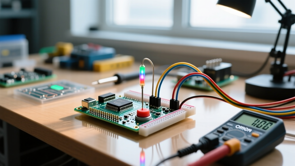
- Omron B3F-1000 Series: Priced around $0.18 per unit in bulk, these 12mm tactile switches feature a specialized contact geometry that limits bounce time to under 2ms. The 1.3N operating force provides excellent tactile feedback without causing finger fatigue during repetitive use.
- C&K PTS645 Series: At approximately $0.12 each, these 6mm switches feature gold-plated contacts. This is critical for low-voltage, low-current logic signals (like a 3.3V Arduino input) where standard tin-plated contacts can suffer from oxidation and increased contact resistance over time.
Expert Insight: Never run high-current LED loads directly through a tactile switch. Most 6x6mm switches are rated for a maximum of 50mA at 12VDC. Driving a 1W Cree LED directly through the switch will pit the contacts and weld them shut within a few hundred cycles. Always use the switch for logic signaling only.
Circuit Topology: Internal Pull-Ups and MOSFET Drivers
Workflow optimization also means reducing your Bill of Materials (BOM) and breadboard clutter. The traditional Arduino button LED tutorial often instructs users to wire an external 10kΩ pull-down resistor. This is unnecessary and wastes prototyping time.
Leveraging INPUT_PULLUP
The ATmega328P and Renesas RA4M1 (found in the Uno R4) feature internal pull-up resistors ranging from 32kΩ to 50kΩ. By configuring your pin mode as INPUT_PULLUP and wiring the button directly between the digital pin and ground, you invert the logic (LOW = pressed, HIGH = released) but eliminate the need for external resistors. This cuts wiring time by 30% and reduces points of failure on the breadboard.
Driving the LED: The 2N7000 MOSFET Workflow
When your LED requires more than 15mA (the safe continuous limit for most MCU GPIO pins), introduce a 2N7000 N-channel MOSFET. Costing roughly $0.08 in 2026, the 2N7000 can handle up to 200mA. Wire the Arduino output pin to the MOSFET gate via a 220Ω resistor, tie the source to ground, and connect the LED in series with a current-limiting resistor to the drain. This isolates your delicate microcontroller silicon from inductive spikes and thermal stress, drastically improving long-term project reliability.
The Debounce Matrix: Choosing the Right Strategy
Debouncing is the process of filtering out the mechanical noise of a switch. According to embedded systems expert Jack Ganssle in his definitive Guide to Debouncing, there is no one-size-fits-all solution. The optimal choice depends on your CPU overhead and BOM constraints.
| Debounce Method | CPU Blocking? | BOM Cost Impact | Implementation Time | Reliability & Edge Cases |
|---|---|---|---|---|
| Hardware RC Filter (10kΩ + 100nF) | No | +$0.05 per node | High (Wiring) | Excellent. Eliminates noise before it reaches the MCU. Requires a Schmitt trigger for slow edges. |
Software Delay (delay(50)) |
Yes | $0.00 | Low (1 line) | Poor. Freezes the MCU, dropping serial data and missing secondary button presses. |
Software Timer (millis()) |
No | $0.00 | Medium | High. Industry standard for non-blocking firmware. Requires careful variable management. |
| Library (e.g., Bounce2) | No | $0.00 | Low | Very High. Abstracts timer logic and handles edge detection (rising/falling) automatically. |
Software Architecture: The Non-Blocking State Machine
To achieve a truly optimized Arduino button LED workflow, you must abandon linear scripting and adopt a non-blocking state machine. The official Arduino Debounce Tutorial provides a basic timer approach, but for complex workflows, a formal state machine is superior.
The Millis() Rollover Trap
When using millis() for timing, a common bug occurs when the 32-bit unsigned integer rolls over to zero after approximately 49.7 days. If your code uses addition to calculate the target time (if (currentMillis >= previousMillis + interval)), it will fail catastrophically at rollover. Always use subtraction: if (currentMillis - previousMillis >= interval). Because unsigned integer math wraps around naturally, this subtraction method is mathematically immune to the 49.7-day rollover bug.
Implementing the State Machine
Structure your loop() function to evaluate states rather than execute sequential actions. Here is the architectural flow for an optimized toggle:
- Read Input: Poll the
INPUT_PULLUPpin. - Debounce Check: Compare current
millis()against the last state change timestamp. If the difference is less than 50ms, ignore the input. - Edge Detection: Compare the current stable reading to the previous stable reading. A transition from HIGH to LOW indicates a confirmed button press.
- State Transition: Toggle the LED state variable and update the GPIO pin via
digitalWrite(). - Timestamp Update: Record the current
millis()as the new baseline for the next debounce cycle.
By encapsulating this logic into a custom class or utilizing the highly optimized Bounce2 library, your main loop remains completely unblocked, allowing you to run PID controllers, update OLED displays, or stream telemetry data concurrently without missing a single button press.
Advanced Workflow: Long-Distance Wiring and Noise Immunity
As your project moves from the breadboard to a physical enclosure, wire length introduces capacitance and electromagnetic interference (EMI). A 3-foot run of 24 AWG wire to a remote button can act as an antenna, picking up 60Hz mains hum and triggering false LED toggles.
To optimize for physical deployment:
- Lower the Pull-Up Resistance: Disable the internal 50kΩ pull-up and use an external 4.7kΩ resistor. This creates a stronger, lower-impedance circuit that is highly resistant to capacitive noise coupling.
- Twisted Pair Routing: Route the button signal wire alongside a ground wire, twisting them together. This cancels out common-mode EMI.
- Software Hysteresis: Require the button to read LOW for three consecutive polls (spaced 5ms apart) before registering a press. This digital filtering eliminates high-frequency noise spikes that hardware RC filters might miss.
Conclusion: Engineering the Mundane
Treating the Arduino button LED circuit as a trivial exercise is a missed opportunity to practice robust embedded systems engineering. By selecting premium components like Omron switches, utilizing internal pull-ups, isolating LED loads with MOSFETs, and implementing non-blocking state machines, you transform a basic tutorial into a production-grade HMI workflow. These optimization techniques not only save time during the prototyping phase but ensure your firmware remains stable, responsive, and scalable as your project complexity grows.