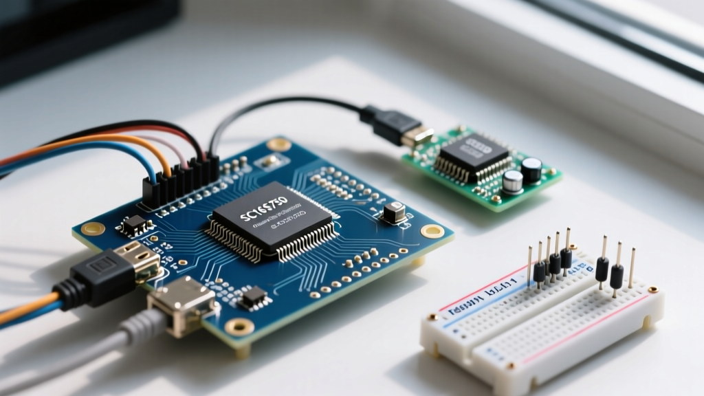

When you run out of hardware UART ports on an ESP32 or need to route a serial GPS module over a shared I2C bus to a Raspberry Pi, you need a UART to I2C bridge. This isn't a simple wire crossover; it requires a dedicated bridge IC like the NXP SC16IS750 to translate asynchronous serial data into synchronous, register-based I2C packets. Below is the bench-tested guide to wiring, coding, and debugging this translation layer.
The Physical Layer: Wiring UART to I2C Bridge ICs
Before writing a single line of code, you must respect the physical realities of both buses. I2C is a synchronous, multi-drop bus that requires external pull-up resistors. UART is an asynchronous, point-to-point bus that relies on agreed-upon timing (baud rate) and crossed TX/RX lines. The bridge IC sits in the middle, buffering UART bytes into an internal FIFO and exposing them as I2C registers.
| Characteristic | I2C (Controller Side) | UART (Peripheral Side) |
|---|---|---|
| Wires | 2 (SDA, SCL) + GND | 2 (TX, RX) + GND |
| Speed | 100 kHz (Standard) to 1 MHz (Fast+) | 9600 to 115200 baud (typical) |
| Addressing | 7-bit or 10-bit hardware address | None (Point-to-point) |
| Topology | Multi-drop bus (up to 127 devices) | Strictly 1-to-1 connection |
| Max Distance | ~30 cm (without bus extenders) | ~15 meters (at 9600 baud) |
The I2C side of your bridge must have pull-up resistors on SDA and SCL. For standard 100 kHz operation, use 4.7 kΩ resistors tied to VCC (3.3V). If you push the I2C bus to 400 kHz Fast Mode to keep up with a 115200 baud UART stream, drop the pull-ups to 2.2 kΩ to sharpen the rising edges. Breakout boards like the Adafruit I2C to UART (PID 5786) include these onboard.
Protocol Translation: Bridging the Asynchronous Gap
The NXP SC16IS750 handles the heavy lifting. It uses a 14.7456 MHz crystal to generate precise UART baud rates, completely independent of the I2C clock speed. Your microcontroller acts as the I2C master, writing to the bridge's Line Control Register (LCR) to set the baud rate, and reading from the Receive Holding Register (RHR) to fetch UART bytes.
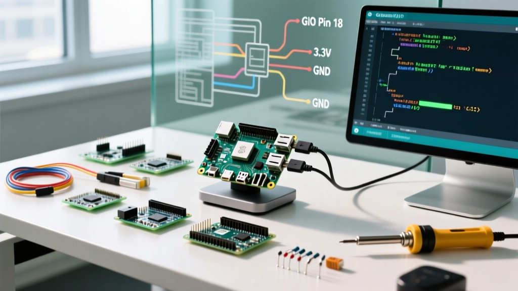
Below is the exact wiring required to interface an ESP32 DevKit V1 with the SC16IS750 breakout, followed by a minimal, non-blocking exchange example.
| ESP32 DevKit V1 Pin | SC16IS750 Breakout Pin | Target UART Device (e.g., GPS) |
|---|---|---|
| GPIO 21 (SDA) | SDA | - |
| GPIO 22 (SCL) | SCL | - |
| 3V3 | VIN / VCC | VCC (if 3.3V device) |
| GND | GND | GND |
| - | TX | RX |
| - | RX | TX |
// ESP32 DevKit V1 - UART to I2C Bridge via SC16IS750
// Requires: Adafruit SC16IS750 Library
#include <Wire.h>
#include <Adafruit_SC16IS750.h>

// Default I2C address for SC16IS750 (A0 and A1 pins grounded)
#define SC16IS750_ADDR 0x48

Adafruit_SC16IS750 uart_bridge = Adafruit_SC16IS750();

void setup() {
  Serial.begin(115200);

  // Initialize I2C bus on ESP32 default pins (21=SDA, 22=SCL)
  Wire.begin();

  if (!uart_bridge.begin(SC16IS750_ADDR, &Wire)) {
    Serial.println("FATAL: SC16IS750 not found. Check I2C wiring and pull-ups.");
    while (1) { delay(10); }
  }

  // Configure the UART side of the bridge
  uart_bridge.begin(9600); // Set baud rate for the attached UART device
  Serial.println("Bridge initialized. Listening for UART data...");
}

void loop() {
  // Non-blocking read from the bridge's internal FIFO
  if (uart_bridge.available()) {
    char c = uart_bridge.read();
    Serial.print(c); // Forward to ESP32 hardware USB serial
  }

  // Pass-through: Send USB serial commands out through the bridge
  if (Serial.available()) {
    uart_bridge.write(Serial.read());
  }
}
Debugging the Bridge: Sniffing and Fixing Classic Failures
When a UART to I2C bridge fails, the symptom is usually silent hangs or garbage data. Because you are crossing two different physical layers, you must isolate the fault domain. Here are the three most common failures and how to fix them.
1. The Missing Pull-Up (I2C Bus Hang)
If your code hangs on Wire.endTransmission() or the bridge fails to initialize, your I2C bus is likely missing pull-up resistors. Measure SDA and SCL with a multimeter relative to GND while the bus is idle. Both should read a solid 3.3V. If they read 0V or float around 1.2V, the bus is stuck or floating. Solder 4.7 kΩ resistors between the SDA/SCL lines and the 3.3V rail.
2. Address Clash on the Bridge IC
The SC16IS750 has two address pins (A0 and A1). If you leave them floating, they often default to ground, yielding an I2C address of 0x48. If you put two bridge breakouts on the same bus without configuring these pins, they will clash. Use the i2cdetect -y 1 command on a Raspberry Pi, or an I2C scanner sketch on Arduino, to verify the address.
| A1 Pin State | A0 Pin State | Resulting 7-Bit Address |
|---|---|---|
| GND | GND | 0x48 |
| GND | VCC | 0x49 |
| VCC | GND | 0x4A |
| VCC | VCC | 0x4B |
3. Baud Rate Mismatch and Garbage Characters
If your serial monitor outputs scrambled symbols (e.g., ÿÿÿ), the UART baud rate on the bridge does not match the peripheral device. The SC16IS750 derives its baud rate from its onboard crystal (typically 14.7456 MHz). If you are using a clone board with a 1.8432 MHz crystal, the internal baud rate divisor math in standard libraries will be wrong, resulting in a massive timing skew. Verify the crystal frequency printed on the metal can and adjust the library's clock speed definition if necessary.
How to Sniff the Bus:
To definitively debug a translation failure, use a logic analyzer (like a Saleae Logic Pro 8 or DSLogic Plus). Connect channels 0-1 to SDA/SCL and channels 2-3 to UART TX/RX. Set the analyzer to trigger on the I2C Start condition. Decode both protocols simultaneously in the software. This allows you to see exactly which I2C register write correlates to the malformed UART byte on the wire.
Frequently Asked Questions: UART to I2C Integration
Can I connect multiple UART devices to a single I2C bus using bridges?
Yes, but with caveats. You can place up to four SC16IS750 breakouts on a single I2C bus by configuring the A0 and A1 address pins to unique states (0x48, 0x49, 0x4A, 0x4B). Each bridge provides one independent UART port. However, remember that the total I2C bus capacitance must remain under 400 pF. If you add too many breakouts, the SDA/SCL rising edges will degrade, requiring you to lower the I2C clock speed or use an active bus buffer like the PCA9600.
Why is my UART to I2C bridge returning garbage characters at 9600 baud?
Garbage characters almost always indicate a baud rate mismatch between the bridge IC's configured divisor and the actual peripheral device. First, verify the peripheral is actually set to 9600 baud (some GPS modules default to 115200 or 38400). Second, check the oscillator frequency on the bridge board. The I2C bus specification doesn't dictate UART timing, so the bridge relies entirely on its local crystal. If the library assumes a 14.7456 MHz crystal but the board has a 1.8432 MHz crystal, your actual baud rate will be off by a factor of 8.
How do I interface a 5V UART GPS module with a 3.3V I2C bridge IC?
Never connect a 5V UART TX line directly into the 3.3V RX pin of the SC16IS750; you will fry the bridge's internal FIFO buffer. You must use a bidirectional logic level shifter. A breakout board based on the BSS138 MOSFET (like the Adafruit 4-channel level shifter) is ideal here. Connect the low-voltage side to the bridge's 3.3V TX/RX, and the high-voltage side to the GPS module's 5V TX/RX. Ensure the level shifter has its own pull-up resistors on both voltage domains.
What is the maximum reliable cable length for a UART to I2C setup?
The limitation is the I2C side, not the UART side. Standard I2C is limited to about 30 cm (1 foot) due to bus capacitance and the lack of differential signaling. If you need to place the UART device meters away from your microcontroller, do not run long I2C wires. Instead, place the microcontroller and the I2C-to-UART bridge at the remote location, and use a dedicated I2C bus extender (like the P82B96) or convert the I2C signal to RS-485 for the long-haul run back to the main controller.