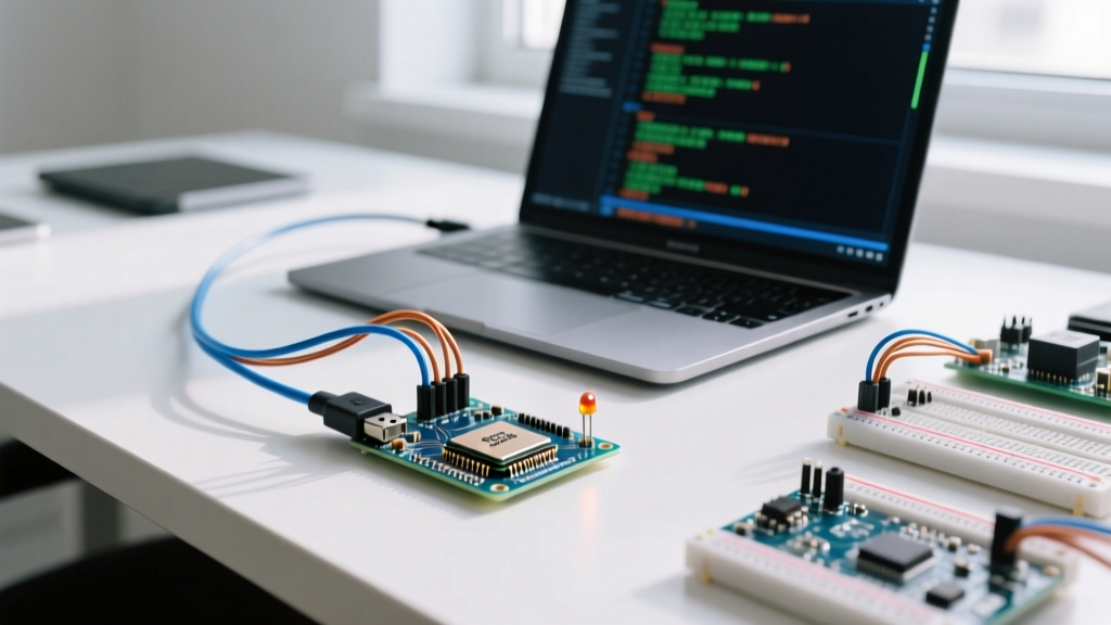
Pulse Width Modulation (PWM) on an Arduino is not true analog output; it is a digital square wave where the duty cycle simulates an average voltage. When you call analogWrite(pin, 127), the microcontroller toggles the pin HIGH and LOW at a specific frequency, spending roughly 50% of the time in the HIGH state. For a 5V logic board, this yields an average of ~2.5V. While this is sufficient for dimming an LED, driving DC motors or proportional valves requires a deeper understanding of hardware timers, frequency selection, and driver IC limitations.
This guide targets the Arduino Uno R3 (ATmega328P). We will map the hardware timers, build a robust motor controller using a modern MOSFET driver, and troubleshoot the exact compiler and hardware faults that stall most embedded projects.
Arduino PWM Pinout and Timer Mapping
Before wiring a single component, you must understand that the Uno R3 does not generate PWM in software. It relies on three hardware timers (Timer0, Timer1, Timer2). Changing the PWM frequency on one pin affects all other pins sharing that same timer. Furthermore, Timer0 is hardcoded by the Arduino core to handle millis(), delay(), and servo.write(). Modifying Timer0's prescaler will break your timing functions.
| Uno R3 Pin | Hardware Timer | Default Frequency | Resolution | Hardware Note / Conflict |
|---|---|---|---|---|
| Pin 5 | Timer 0 (OC0B) | 980 Hz | 8-bit (0-255) | Do not alter. Breaks delay() and millis(). |
| Pin 6 | Timer 0 (OC0A) | 980 Hz | 8-bit (0-255) | Do not alter. Breaks delay() and millis(). |
| Pin 9 | Timer 1 (OC1A) | 490 Hz | 8-bit (0-255)* | 16-bit timer. Safe to change prescaler for higher frequency. |
| Pin 10 | Timer 1 (OC1B) | 490 Hz | 8-bit (0-255)* | Shares Timer 1 with Pin 9. Also used by default SPI SS. |
| Pin 3 | Timer 2 (OC2B) | 490 Hz | 8-bit (0-255) | 8-bit timer. Often used for audio tone generation. |
| Pin 11 | Timer 2 (OC2A) | 490 Hz | 8-bit (0-255) | Shares Timer 2 with Pin 3. Also used by default SPI MOSI. |
*Note: While Timer1 is a 16-bit hardware timer, the standard Arduino analogWrite() function artificially restricts it to 8-bit resolution for API consistency. You can unlock 16-bit resolution by writing directly to the OCR1A/OCR1B registers.
Project: TB6612FNG Motor Controller with Fault Handling
The classic L298N motor driver is a relic. It uses a bipolar junction transistor (BJT) H-bridge that drops up to 2V across the IC at moderate loads, wasting power as heat. For modern Arduino PWM motor control, the Toshiba TB6612FNG is the superior choice. It uses MOSFETs, dropping only ~0.5V at 1A, and supports PWM switching frequencies up to 100 kHz.
Parts List & Specifications
- Microcontroller: Arduino Uno R3 (ATmega328P, 5V logic)
- Motor Driver: Pololu TB6612FNG Dual Motor Driver Carrier (Item #713)
- Actuator: 12V DC Gear Motor (e.g., JGB37-520, 100 RPM, 1A stall current)
- Power Supply: 12V 3A DC Switching Supply (barrel jack to terminal block)
- Current Sensor: ACS712 5A Current Sensor Module (for overcurrent fault handling)
- Wiring: 22 AWG solid-core jumper wires, 18 AWG stranded for motor power
Pin Mapping Table
| TB6612FNG Pin | Arduino Uno R3 Pin | Function |
|---|---|---|
| VCC | 5V | Logic power (Must be 2.7V - 5.5V) |
| GND | GND | Common logic ground |
| STBY | Pin 10 (Digital) | Standby mode (HIGH = Active, LOW = Sleep) |
| PWMA | Pin 9 (PWM) | Channel A Speed Control (Timer1) |
| AIN1 | Pin 7 (Digital) | Channel A Direction Logic 1 |
| AIN2 | Pin 8 (Digital) | Channel A Direction Logic 2 |
| VM | 12V PSU (+) | Motor high-side voltage (Max 15V) |
| A01 / A02 | Motor Terminals | Channel A Output to Motor |
Wiring Steps
- De-energize the 12V supply. Connect the 12V PSU positive to the TB6612FNG
VMpin and the PSU ground to the driver'sPGND(Power Ground). - Connect the Arduino
5Vto the driverVCC, and ArduinoGNDto the driverGND(Logic Ground). Do not confuse PGND and GND on the breakout; they must both be tied to the system ground plane. - Wire the STBY pin to Arduino Pin 10. If you leave STBY floating, the internal pull-down will keep the driver in sleep mode.
- Connect the ACS712 current sensor in series with the motor's positive lead. Wire the ACS712
OUTpin to ArduinoA0. - Connect PWMA to Pin 9, AIN1 to Pin 7, and AIN2 to Pin 8.
Complete Compilable Code (Target: Uno R3)
This firmware implements a soft-start ramp to prevent inrush current spikes, directional control, and an overcurrent fault shutdown. It targets the Arduino Uno R3 (AVR architecture).
// Target Board: Arduino Uno R3 (ATmega328P)
// Driver: TB6612FNG | Sensor: ACS712 (5A version)

#define PWMA_PIN 9
#define AIN1_PIN 7
#define AIN2_PIN 8
#define STBY_PIN 10
#define CURRENT_SENSE_PIN A0

// ACS712 5A Sensitivity is 185mV/A. Offset is VCC/2 (2.5V).
// At 5V VCC, analogRead(2.5V) = 512.
#define ZERO_CURRENT_OFFSET 512
#define SENSITIVITY_MV 185
#define OVERCURRENT_LIMIT_AMPS 2.5

bool faultState = false;

void setup() {
  Serial.begin(115200);
  pinMode(PWMA_PIN, OUTPUT);
  pinMode(AIN1_PIN, OUTPUT);
  pinMode(AIN2_PIN, OUTPUT);
  pinMode(STBY_PIN, OUTPUT);

  // Wake up the TB6612FNG
  digitalWrite(STBY_PIN, HIGH);

  // Set initial direction (Forward)
  digitalWrite(AIN1_PIN, HIGH);
  digitalWrite(AIN2_PIN, LOW);

  Serial.println("System Initialized. Ramping up...");
}

void loop() {
  if (faultState) {
    // Halt motor and blink STBY to indicate fault
    analogWrite(PWMA_PIN, 0);
    digitalWrite(STBY_PIN, millis() % 500 < 250 ? HIGH : LOW);

    // Check if user sent 'R' via Serial to reset fault
    if (Serial.available() && Serial.read() == 'R') {
      faultState = false;
      digitalWrite(STBY_PIN, HIGH);
      Serial.println("Fault Cleared. Resuming.");
    }
    return;
  }

  // Soft-start ramp (0 to 200 duty cycle over 2 seconds)
  static unsigned long lastRampTime = 0;
  static int currentPWM = 0;

  if (currentPWM < 200 && millis() - lastRampTime > 10) {
    currentPWM++;
    analogWrite(PWMA_PIN, currentPWM);
    lastRampTime = millis();
  }

  // Read Current Sensor (Average 10 samples for noise reduction)
  long sensorSum = 0;
  for (int i = 0; i < 10; i++) {
    sensorSum += analogRead(CURRENT_SENSE_PIN);
  }
  int sensorValue = sensorSum / 10;

  // Calculate actual current
  float voltage = (sensorValue - ZERO_CURRENT_OFFSET) * (5.0 / 1024.0);
  float currentAmps = (voltage * 1000.0) / SENSITIVITY_MV;

  // Fault Handling
  if (abs(currentAmps) > OVERCURRENT_LIMIT_AMPS) {
    Serial.print("OVERCURRENT FAULT: ");
    Serial.print(currentAmps);
    Serial.println("A. Shutting down.");
    faultState = true;
  }

  // Telemetry output (throttled to 2Hz)
  static unsigned long lastPrint = 0;
  if (millis() - lastPrint > 500) {
    Serial.print("PWM: "); Serial.print(currentPWM);
    Serial.print(" | Current: "); Serial.print(currentAmps, 2); Serial.println("A");
    lastPrint = millis();
  }
}
Debugging: When PWM Fails or Throws Errors
Embedded motor control rarely works perfectly on the first power-up. If your motor twitches, whines, or the code fails to compile, follow this diagnostic decision tree.
The First Three Things to Check
- The STBY Pin State: The TB6612FNG has an internal pull-down resistor on the STBY pin. If your jumper wire to Pin 10 is loose or unconnected, the chip defaults to low-power sleep mode. Multimeter check: Read DC voltage between STBY and GND. It must read ~5V when active.
- Timer0 Conflicts (The 'Twitch' Bug): If you are using
delay()inside your main loop while driving a motor on Pin 5 or 6, the motor will stutter.delay()relies on Timer0 interrupts. Move your PWM output to Pin 9 or 10 (Timer1) to isolate motor control from system timing. - Common Ground Reference: The Arduino, the TB6612FNG logic ground, the TB6612FNG power ground, and the 12V PSU negative must all share a single equipotential ground plane. If the motor ground is isolated from the Arduino ground, the PWM logic signals will float, resulting in erratic switching.
Common Compiler Errors and Fixes
error: 'analogWriteResolution' was not declared in this scopeCause: You copied code written for an Arduino Due, Zero, or Uno R4 Minima. The ATmega328P (Uno R3) is strictly an 8-bit microcontroller with fixed 8-bit PWM resolution (0-255). It does not support the
analogWriteResolution() API.Fix: Delete the
analogWriteResolution() call. Ensure all your analogWrite() values are mapped between 0 and 255.
error: 'TCCR1A' was not declared in this scopeCause: You are trying to manipulate AVR hardware timer registers (like
TCCR1A or OCR1A) to change the PWM frequency, but you have switched your board target in the IDE to an ESP32 or ARM-based board.Fix: If targeting ESP32, abandon AVR register manipulation. Use the ESP32 LEDC peripheral API (
ledcSetup() and ledcAttachPin()). If targeting Uno R3, ensure 'Arduino Uno' is selected in Tools > Board.
Hardware Symptom: Motor Whines but Won't Turn
If the motor emits a high-pitched squeal but the shaft doesn't rotate, your PWM duty cycle is high enough to energize the coils, but too low to overcome the static friction (stiction) of the gearbox. DC motors have a 'minimum start voltage'. If 12V is required to run it, it might need 4V just to start.
The Fix: Implement a 'kickstart' routine in your code. Apply 100% PWM (255) for 50 milliseconds to break stiction, then immediately drop to your desired lower PWM value.
Extending and Simplifying the Build
Once the baseline Uno R3 and TB6612FNG circuit is proven, you will inevitably need to scale the project. Here is how to adapt the architecture.
Scaling Up: Migrating to ESP32
If you need WiFi telemetry or higher PWM frequencies to eliminate motor whine entirely, migrate to an ESP32-WROOM-32. The ESP32 uses the LEDC (LED Control) peripheral, which is entirely decoupled from the CPU timers.
- Advantage: You can set the PWM frequency to 20 kHz (ultrasonic, silent operation) and use 12-bit resolution (0-4095) for ultra-fine speed control.
- Gotcha: The ESP32 is a 3.3V logic device. While the TB6612FNG accepts 2.7V logic, the ACS712 current sensor is a 5V analog device. You must use a voltage divider or a logic-level op-amp to scale the ACS712 analog output down to the ESP32's 0-3.3V ADC range, or you will permanently damage the ESP32 GPIO.
Scaling Down: ATTiny85 for Standalone Control
If the project is a simple, single-direction fan controller and you want to eliminate the bulky Uno, port the design to an ATTiny85.
- Advantage: Costs under $2.00, fits on a perfboard the size of a postage stamp.
- Gotcha: The ATTiny85 only has two hardware timers. Timer0 is still used for
millis(). You must use Pin 1 (OC1A) or Pin 4 (OC1B) for PWM. Furthermore, the ADC is 10-bit but much noisier than the Uno's; you will need heavy software averaging (as shown in the code above) for the current sense feedback loop.
Driver Comparison: TB6612FNG vs L298N vs DRV8871
| Feature | TB6612FNG (Dual) | L298N (Dual) | DRV8871 (Single) |
|---|---|---|---|
| Architecture | MOSFET H-Bridge | BJT H-Bridge | MOSFET H-Bridge |
| Voltage Drop @ 1A | ~0.5V | ~2.0V | ~0.4V |
| Max Continuous Current | 1.2A (per channel) | 2.0A (per channel) | 3.6A |
| Max PWM Frequency | 100 kHz | 25 kHz | 50 kHz |
| Logic Voltage | 2.7V - 5.5V | 5V - 7V (Logic) | 2.2V - 5.5V |
| Best Use Case | Robotics, dual small motors | Legacy projects, high current 12V | Single large motor, high torque |
By understanding the underlying hardware timers and selecting a MOSFET-based driver like the TB6612FNG, you eliminate the thermal throttling and audible noise that plague beginner motor control projects. Always verify your logic levels, isolate your timing-critical pins, and implement software current limits to protect your silicon.
Sources:
Arduino Official Reference: analogWrite()
Pololu TB6612FNG Dual Motor Driver Carrier Datasheet
Arduino Foundations: Secrets of PWM