
The Anatomy of a Potentiometer Circuit
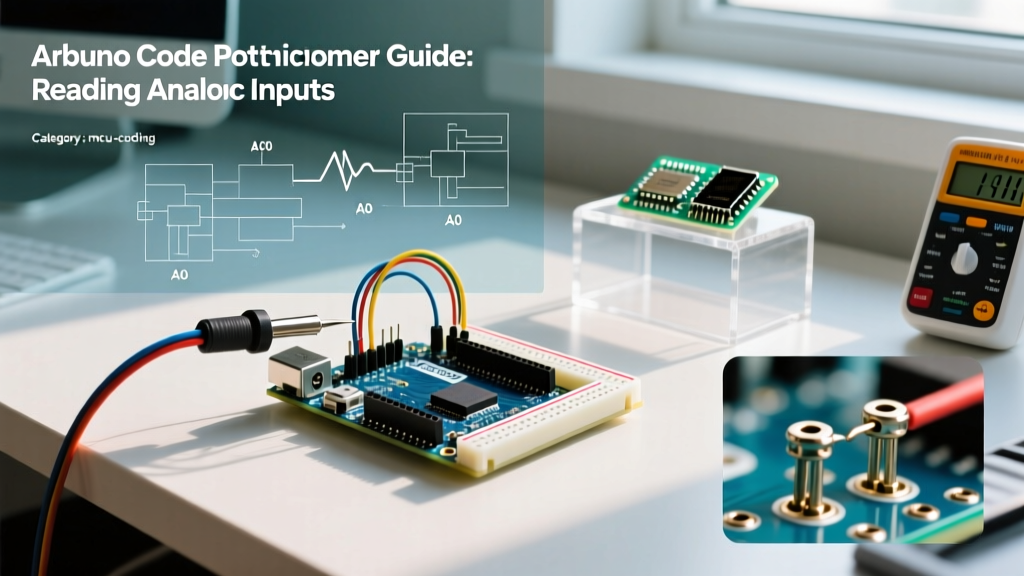
A potentiometer is fundamentally a three-terminal variable resistor that acts as an adjustable voltage divider. For beginners diving into microcontroller programming, it serves as the perfect bridge between physical human input and digital logic. When you turn the knob, you alter the resistance ratio, which in turn changes the voltage presented to the microcontroller's Analog-to-Digital Converter (ADC) pin.
However, writing robust Arduino code for potentiometer inputs requires more than just calling a single read function. Real-world components introduce electrical noise, mechanical jitter, and non-linear voltage curves. In this guide, we will explore the hardware selection, wiring best practices, and the specific C++ code required to achieve buttery-smooth analog readings in 2026.
Selecting the Right Component: B10K vs. A10K
Before writing a single line of code, you must select the correct hardware. Potentiometers come in different resistance 'tapers'. The two most common are:
- Linear Taper (B10K): The resistance changes at a constant rate relative to the shaft rotation. A 50% physical turn yields exactly 50% of the total resistance.
- Logarithmic/Audio Taper (A10K): The resistance changes exponentially. This matches human hearing perception for audio volume controls but is disastrous for microcontroller inputs.
Expert Tip: Always purchase B10K (Linear 10,000 Ohm) potentiometers for Arduino projects. Microcontroller ADCs read voltage linearly. If you use an Audio taper, your map() functions will skew heavily to one side of the rotation. A standard Alpha 16mm B10K rotary potentiometer costs roughly $1.25 to $1.80 on DigiKey or Mouser, while a Bourns 3306P 10K trimmer potentiometer costs around $0.85.
Hardware Wiring and the RC Filter Trick
The physical wiring of a potentiometer is straightforward, but adding a passive hardware filter will save you hours of software debugging later. Carbon-track potentiometers are notoriously noisy. As the wiper moves across the carbon element, microscopic dust and wear cause micro-disconnects, resulting in voltage spikes.
| Potentiometer Pin | Arduino Pin | Function | Notes |
|---|---|---|---|
| Pin 1 (CCW) | 5V | Voltage Reference | Provides the upper bound for the voltage divider. |
| Pin 2 (Wiper) | A0 | Analog Signal Input | The middle pin; outputs the variable voltage. |
| Pin 3 (CW) | GND | Ground Return | Provides the 0V lower bound. |
🛠️ Hardware Pro-Tip: The 100nF Capacitor Trick
Solder a 0.1µF (100nF) ceramic capacitor directly between the Wiper (Pin 2) and GND (Pin 3) on the back of the potentiometer. This creates a passive low-pass RC filter. With a 10K potentiometer, the cutoff frequency is roughly 159Hz, which instantly filters out high-frequency electromagnetic interference (EMI) and carbon-track scratch noise before it ever reaches the Arduino's ADC pin.
Writing the Core Arduino Code for Potentiometer Inputs
The foundational function for reading analog voltage in the Arduino ecosystem is analogRead(). According to the official Arduino analogRead() reference, this function reads the value from the specified analog pin.
On a classic Arduino Uno R3, the ADC is 10-bit, meaning it maps the 0-5V range to integer values between 0 and 1023. On the newer Arduino Uno R4 Minima, the ADC is 12-bit (configurable up to 14-bit), mapping 0-3.3V to 0 and 4095. For this guide, we will write code optimized for the standard 10-bit (0-1023) architecture, which remains the baseline for most beginner tutorials.
// Basic Potentiometer Read Sketch
const int potPin = A0;
int rawValue = 0;

void setup() {
  Serial.begin(115200);
  // No pinMode required for analogRead() on standard AVR boards
}

void loop() {
  rawValue = analogRead(potPin);

  // Calculate actual voltage (5V reference / 1024 steps)
  float voltage = rawValue * (5.0 / 1023.0);

  Serial.print("Raw ADC: ");
  Serial.print(rawValue);
  Serial.print(" | Voltage: ");
  Serial.println(voltage);

  delay(100); // Slow down serial output for readability
}
Solving ADC Jitter: Software Smoothing
Even with a hardware capacitor, you may notice the raw ADC value fluctuating by ±2 or ±3 digits when the knob is perfectly still. This is caused by thermal noise and internal ADC reference variations. To fix this, we implement a Moving Average Filter in our Arduino code.
Instead of reading the pin once, we read it multiple times, store the values in an array, and average them. This sacrifices a tiny amount of sampling speed for massive gains in stability.
// Moving Average Smoothing Filter
const int potPin = A0;
const int numReadings = 20; // Number of samples to average
int readings[numReadings];
int readIndex = 0;
long total = 0;
int average = 0;

void setup() {
  Serial.begin(115200);
  // Initialize all elements of the array to 0
  for (int thisReading = 0; thisReading < numReadings; thisReading++) {
    readings[thisReading] = 0;
  }
}

void loop() {
  // Subtract the last reading from the total
  total = total - readings[readIndex];

  // Read the new value from the sensor
  readings[readIndex] = analogRead(potPin);

  // Add the new reading to the total
  total = total + readings[readIndex];

  // Advance to the next position in the array
  readIndex = readIndex + 1;

  // If we're at the end of the array, wrap around to the beginning
  if (readIndex >= numReadings) {
    readIndex = 0;
  }

  // Calculate the average
  average = total / numReadings;

  Serial.println(average);
  delay(10); // 10ms delay for stability
}
As detailed in the Arduino Basic Analog Input tutorial, smoothing is critical when your potentiometer is controlling sensitive outputs like servo motors or audio DACs, where a jitter of 3 ADC steps translates to visible twitching or audible static.
Mapping Values to Real-World Outputs
Raw ADC values (0-1023) are rarely useful on their own. You usually need to scale them to match a specific output protocol. The map() function is your best friend here, but it must be paired with constrain() to prevent out-of-bounds errors caused by slight voltage overruns.
Common Mapping Scenarios
- LED Dimming (PWM): Map 0-1023 to 0-255 for the
analogWrite()function.
int pwmValue = map(average, 0, 1023, 0, 255); - Servo Motor Control: Map 0-1023 to 0-180 degrees.
int servoAngle = map(average, 0, 1023, 0, 180); - Motor Speed (Percentage): Map 0-1023 to 0-100 for UI displays.
int speedPercent = map(average, 0, 1023, 0, 100);
Crucial Edge Case: The map() function does not prevent numbers from exceeding the target bounds if the input exceeds the expected range. Always wrap your mapped value in constrain(val, min, max) before sending it to a hardware pin.
Troubleshooting Common Analog Read Failures
When your Arduino code potentiometer setup behaves erratically, the issue is almost always physical rather than logical. Here is a diagnostic framework for the most common failure modes.
1. The 'Reversed Logic' Problem
Symptom: Turning the knob clockwise decreases your mapped value instead of increasing it.
Cause: You have wired Pin 1 (5V) and Pin 3 (GND) backward.
Fix: You can physically swap the wires, or simply reverse the map() function in your code: map(average, 0, 1023, 255, 0). This is a common technique when designing custom MIDI controllers where panel layout dictates inverted wiring.
2. Floating Ground Noise
Symptom: The serial monitor prints random numbers between 0 and 1023 even when the potentiometer is disconnected or untouched.
Cause: The GND pin is not properly connected, leaving the ADC pin 'floating' and acting as an antenna for 50/60Hz mains hum.
Fix: Verify continuity between the Arduino GND and the potentiometer Pin 3 using a multimeter. Ensure your USB cable is properly shielded.
3. Dead Zones at the Edges
Symptom: The value gets stuck at 1020 and won't reach 1023, or bottoms out at 3 instead of 0.
Cause: Cheap carbon-track potentiometers (often found in sub-$1 starter kits) suffer from poor end-point wiper contact. Furthermore, if you are powering the Arduino via USB, the 5V rail might actually be 4.7V, skewing the ADC reference.
Fix: Use the Bourns 3306 series or higher-grade Alpha pots for full-range travel. In code, implement a software deadzone: if the value is > 1015, force it to 1023.
// Implementing Software Edge Deadzones
if (average >= 1015) {
  average = 1023;
} else if (average <= 8) {
  average = 0;
}
Summary
Mastering analog inputs is a rite of passage for embedded systems programmers. By selecting a linear B10K potentiometer, adding a 100nF hardware filter, and implementing a moving-average algorithm in your Arduino code, you transform a noisy, jittery component into a precision control interface. Whether you are building a DIY MIDI synthesizer, a robotic arm controller, or a simple dimmable LED lamp, these foundational techniques will ensure your physical inputs translate into flawless digital logic.