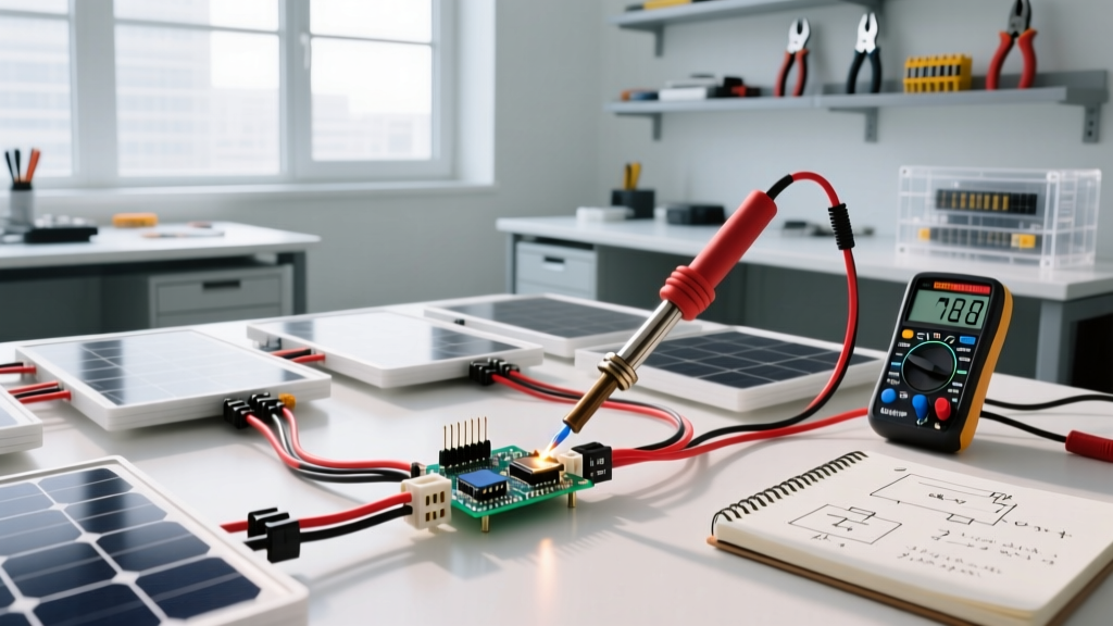

Wiring solar panels in parallel keeps the array voltage at the level of a single panel while summing the current (amperage) of all connected panels. This configuration is ideal for 12V or 24V battery systems using PWM charge controllers, or for heavily shaded roofs where maintaining independent panel output is critical. The complete system block flows from the PV array through MC4 combiner boxes into the MPPT or PWM charge controller, then to the battery bank busbars, and finally to the DC-to-AC inverter feeding your AC loads.
While series wiring is the default for modern high-voltage MPPT arrays, parallel wiring remains a foundational technique for specific off-grid, marine, and RV applications. Below is the exact math, component sizing, and code-compliant wiring methodology required to design a parallel PV array.
Series vs. Parallel: Voltage, Current, and Ah Consequences
The fundamental difference between series and parallel wiring dictates how your charge controller interacts with the battery bank. When you wire solar panels in parallel, the voltage (Vmp) remains constant, but the current (Imp) adds together. Conversely, wiring in series adds the voltage while keeping the current constant.
A common point of confusion is the consequence for battery Amp-hours (Ah). Wiring panels in parallel does not change the physical Ah capacity of your battery bank. However, it directly increases the charge current delivered to the battery. Higher charge current fills the battery's Ah capacity faster, reducing the time required to reach full state-of-charge (SoC). Series wiring, on the other hand, increases voltage to overcome the battery's resting voltage plus the MPPT controller's overhead, allowing for smaller wire gauges over long distances.
| Configuration | Array Vmp | Array Imp | Array Isc | Min. PV Wire (AWG) | Best Controller Type |
|---|---|---|---|---|---|
| 4 in Series (4S) | 160V | 10A | 11A | 14 AWG | MPPT (150V+ limit) |
| 4 in Parallel (4P) | 40V | 40A | 44A | 6 AWG | PWM or Low-V MPPT |
| 2 Series, 2 Parallel (2S2P) | 80V | 20A | 22A | 10 AWG | MPPT (100V limit) |
Note: Wire sizing assumes copper THHN in conduit with a standard 3% voltage drop limit and NEC 125% continuous current derating applied to the Isc values.
Sizing Math: Charge Limits, Peukert, and Efficiency Factors
To properly size the battery bank and downstream components, we must calculate the actual DC load and apply efficiency derating. Let's design a system for a continuous 1200W off-grid cabin load running for 4 hours.
1. Inverter DC Draw Calculation:
AC Load: 1200W
Inverter Efficiency: 90% (0.90)
DC Draw = 1200W / (12V * 0.90) = 111.1 Amps continuous.
2. Battery Bank Sizing (Lithium vs. Lead-Acid):
Total Ah Required = 111.1A * 4 hours = 444.4 Ah at 100% Depth of Discharge (DoD).
For a LiFePO4 battery, the standard usable DoD is 80% (0.80).
LiFePO4 Bank Size = 444.4 Ah / 0.80 = 555 Ah (e.g., two 12V 300Ah LiFePO4 batteries in parallel).
If you were using AGM Lead-Acid batteries, you must apply Peukert's Law. Peukert's exponent (typically k ≈ 1.3 for AGM) dictates that higher discharge rates exponentially reduce usable capacity. Pulling 111A from a 444Ah AGM bank (a 0.25C rate) yields an effective capacity of only about 70%. Factoring in the 50% maximum DoD for lead-acid longevity, you would need roughly 1,200 Ah of rated AGM capacity to deliver the same usable energy as 555 Ah of lithium.
3. Charge and Discharge Limits (C-Rates):
Most LiFePO4 cells have a maximum continuous discharge C-rate of 1C and a maximum charge C-rate of 0.5C. For a 300Ah battery, the max discharge is 300A (well above our 111A draw), and the max charge current is 150A. Your solar array and charge controller must not exceed this 150A charge limit, or the Battery Management System (BMS) will disconnect the cells to prevent damage.
Inverter and Charge Controller Sizing for the Stated Load
With the battery and load defined, we must size the inverter and match the parallel solar array to the correct charge controller.
Inverter Sizing:
Continuous load is 1200W. Applying the standard 1.25x safety margin for continuous loads (aligned with NEC Article 210 guidelines for continuous duty), we need 1200W * 1.25 = 1500W minimum. A 2000W 12V Pure Sine Wave Inverter (such as the Victron MultiPlus 12/2000 or a comparable Growatt model) provides the necessary headroom for inductive surge loads like refrigerator compressors or well pumps.
Charge Controller Sizing:
Assume we are using the 4-Panel Parallel (4P) configuration from our earlier table: 4x 400W panels.
Array Isc (Short Circuit Current) = 11A * 4 = 44A.
Per NEC Article 690.8(A), solar PV circuits are considered continuous loads and must be sized at 125% of the Isc.
Required Controller Current Rating = 44A * 1.25 = 55 Amps.
A standard 40A or 50A MPPT controller will clip the excess power or trip its internal breaker. You must select a 60A MPPT Charge Controller (e.g., Victron SmartSolar 100/60). Because the parallel array Vmp is only 40V, the 100V maximum PV input limit of the controller is perfectly safe, even accounting for cold-temperature voltage creep.
PV Wiring and Combiner Box:
Running 55A from the roof combiner box to the charge controller requires heavy copper. To maintain a voltage drop under 3% over a 30-foot run, you must use 4 AWG USE-2 or THWN-2 wire. Fusing is also mandatory: each parallel panel string must have its own 15A inline MC4 fuse, and the main combiner output requires a 60A DC breaker or Class T fuse before entering the charge controller.
Decision Tree: When to Wire Solar Panels in Parallel
Choosing between series, parallel, or series-parallel depends entirely on your physical environment and hardware constraints. Use the manufacturer MPPT calculators to verify voltage limits, but rely on this decision matrix for the initial topology design.
| System Condition / Constraint | Recommended Topology | Technical Reasoning |
|---|---|---|
| Heavy partial shading (trees, chimneys, RV vents) | Parallel | Shading on one panel drops its current. In parallel, the unshaded panels continue to output full current. In series, the shaded panel chokes the current for the entire string. |
| Using a PWM Charge Controller | Parallel | PWM controllers cannot step down voltage. Array Vmp must closely match battery voltage (e.g., 40V Vmp for a 12V/24V system). Series wiring would waste the excess voltage as heat. |
| Long wire runs (>50 feet from array to controller) | Series | Higher voltage and lower current drastically reduce I²R power losses, allowing the use of cheaper, thinner wire (e.g., 10 AWG instead of 4 AWG). |
| Using an MPPT Controller with high-voltage limits | Series | MPPT controllers efficiently step down high voltage into high current at the battery. Series wiring maximizes this efficiency and ensures the controller 'wakes up' early in low-light conditions. |
Wiring solar panels in parallel demands thicker wire, larger fuses, and higher-amperage charge controllers, but it provides unmatched resilience in shaded environments and simplifies troubleshooting. By strictly applying NEC 125% derating to your Isc values and respecting the C-rate limits of your battery chemistry, your parallel array will deliver reliable, code-compliant power for decades.