
Anatomy of a Digital Multimeter (DMM)
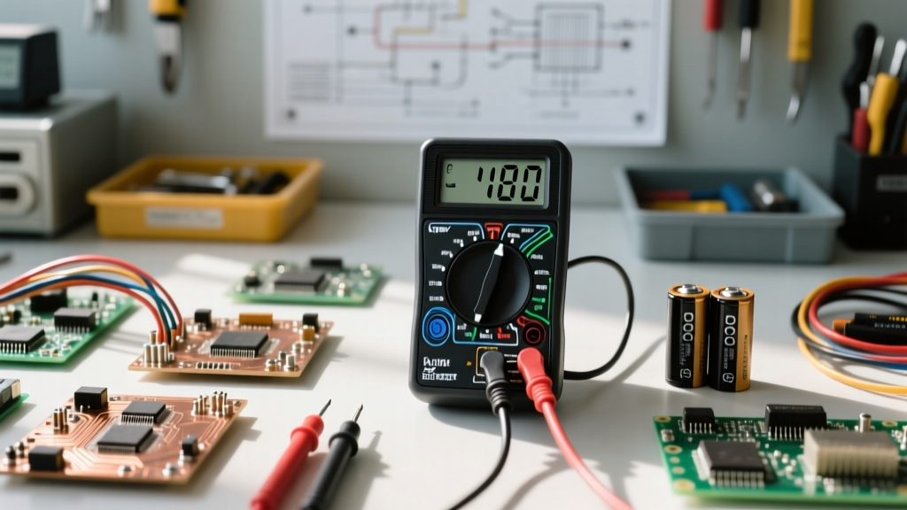
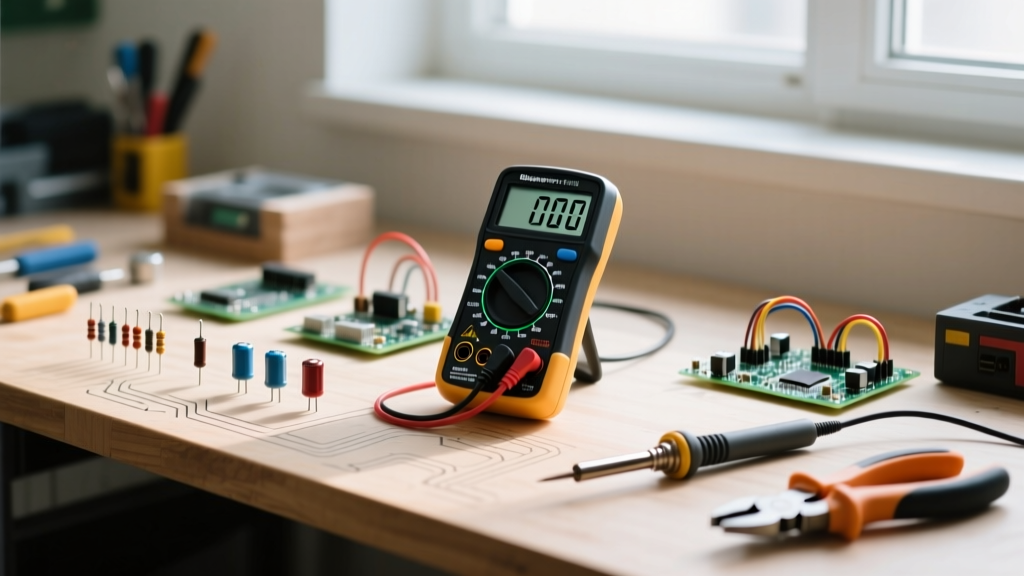
Before using the multimeter on your first circuit, you must understand its physical interface. A standard Digital Multimeter (DMM) consists of three primary components: the display, the selection dial, and the input jacks. The display shows your numerical readout, often accompanied by indicators for battery life or auto-ranging status.
The selection dial is the command center. You will see symbols that correspond to different electrical properties:
- V~ (AC Voltage): Used for wall outlets and mains power.
- V⎓ (DC Voltage): Used for batteries, microcontrollers, and automotive systems.
- Ω (Resistance): Measures the opposition to current flow in a component.
- Diode/Continuity Symbol: Looks like a sound wave or an arrow pointing into a line; used to check if a circuit is complete.
The input jacks are where you connect your test leads. The black lead always goes into the COM (Common) jack. The red lead typically goes into the VΩmA jack for voltage, resistance, and low current. The separate 10A jack is strictly reserved for measuring high currents, a distinction that is critical for safety, which we will cover later.
Safety First: Understanding CAT Ratings and Fusing
When using the multimeter for mains electricity, the internal build quality dictates whether you get a helpful reading or an arc flash. Multimeters are classified by Category (CAT) ratings, which define their transient voltage withstand capabilities.
Rule of Thumb: Never use a CAT II rated meter on a CAT III or CAT IV circuit (like outdoor mains panels or heavy industrial equipment). A transient spike can jump the internal gaps of a cheap meter, causing it to explode in your hands.
High-quality meters from brands like Fluke or Klein Tools utilize HRC (High Rupturing Capacity) fuses. Unlike standard glass fuses found in cheap $15 multimeters, HRC fuses contain sand or special arc-quenching materials that safely contain the explosive energy if you accidentally measure voltage while the probes are plugged into the current jacks.
Step 1: Measuring Voltage (The Most Common Task)
Voltage is the electrical pressure pushing electrons through a circuit. It is always measured in parallel with the component or power source you are testing. This means you do not need to break the circuit to take a reading.
Testing a DC Source (e.g., a 9V Battery)
- Plug the black lead into COM and the red lead into the VΩmA jack.
- Turn the dial to DC Voltage (V⎓). If your meter is manual-ranging, select a range higher than your expected voltage (e.g., the 20V setting for a 9V battery).
- Touch the red probe to the positive (+) terminal and the black probe to the negative (-) terminal.
- If you see a negative sign (e.g., -9.0V), your probes are simply reversed. The magnitude is still correct.
If the display reads OL (Over Limit), your selected range is too low. Turn the dial to a higher voltage setting. For more on basic measurements, refer to the comprehensive SparkFun multimeter tutorial.
Step 2: Testing Continuity (The Circuit Saver)
Continuity testing is arguably the most useful function for DIY electronics and automotive troubleshooting. It tells you if electricity can flow unimpeded from point A to point B. Never test continuity on a live circuit. Always remove power first.
Set your dial to the continuity mode (the sound wave icon). Touch the two probe tips together; you should hear a distinct beep and see a value close to 0.00Ω on the screen. Now, place the probes on either end of a wire, a fuse, or a switch. If it beeps, the path is unbroken. If it remains silent and displays "OL", you have found a broken wire or a blown fuse. This is the fastest way to trace broken traces on a PCB or find a severed wire inside an insulation jacket.
Step 3: Measuring Resistance (Component Health)
Resistance, measured in Ohms (Ω), indicates how much a component fights the flow of electricity. Like continuity, resistance must only be measured on dead circuits. If voltage is present, it will corrupt the reading and potentially fry the meter's internal ADC (Analog-to-Digital Converter).
To measure a resistor, isolate it from the circuit if possible. Measuring a resistor while it is still soldered into a board will often yield a false, lower reading because the meter is measuring the parallel resistance of the surrounding circuit paths. Touch the probes to either leg of the resistor; polarity does not matter here. Compare the reading to the component's color bands or schematic value, keeping in mind that most standard resistors have a tolerance of ±5%.
Step 4: Measuring Current (The Danger Zone)
Measuring current (Amps) is where most beginners destroy their multimeters. Current is the actual flow of electrons, and to measure it, the meter must become part of the circuit. This means you must measure in series, requiring you to physically break the circuit and route the power through the multimeter.
The "Dead Short" Trap
When the red probe is in the current jack (mA or 10A), the multimeter has near-zero internal resistance. If you accidentally touch the probes across a voltage source (in parallel) while in current mode, you create a dead short. The meter will attempt to pull infinite current, instantly blowing its internal fuse. If the meter lacks HRC fuses, the wires can melt or the PCB can catch fire.
For safe current measurement, consult the manufacturer's Fluke guide on multimeter safety to ensure you understand the maximum amperage limits of your specific jacks before breaking the circuit.
Troubleshooting Common Beginner Mistakes
Even experienced technicians make errors when rushing. Below is a breakdown of the most frequent pitfalls encountered when using the multimeter, along with their consequences and solutions.
| Mistake | Consequence | Solution / Prevention |
|---|---|---|
| Measuring voltage with the red probe in the 10A or mA jack. | Creates a dead short; blows the internal fuse or destroys the meter. | Build a habit: immediately move the red probe back to the VΩ jack after finishing a current test. |
| Measuring resistance or continuity on a powered circuit. | False readings, potential damage to the meter's internal circuitry. | Always disconnect the battery or unplug the device before testing passive components. |
| Using a manual-ranging meter on the wrong scale (e.g., 2V scale for a 12V battery). | Display shows "OL" or "1", leading to confusion. | Always start on the highest range setting and work your way down for better resolution. |
| Ignoring low battery warnings on the DMM display. | Inaccurate voltage and resistance readings due to insufficient internal reference voltage. | Replace the 9V or AA batteries immediately when the battery icon appears. |
Recommended Entry-Level Multimeters for DIYers
If you are looking to buy your first reliable tool, avoid the unbranded $10 meters found in checkout aisles. They lack proper safety fusing and exhibit severe measurement drift. Instead, consider these proven models:
- Klein Tools MM400: An excellent auto-ranging meter priced around $45. It handles basic electronics, automotive 12V systems, and standard household AC outlets safely (CAT III 600V).
- AstroAI DM100: A budget-friendly option (under $20) that is perfectly adequate for low-voltage hobby electronics (Arduino, Raspberry Pi, battery testing), though not recommended for mains AC work.
- Fluke 115: The gold standard for professionals and serious hobbyists. Priced around $200, it offers unmatched accuracy, true-RMS capabilities, and bombproof safety ratings. It is a lifetime investment.
Mastering the multimeter is the gateway to independent electronics troubleshooting. By respecting the safety categories, understanding the difference between series and parallel measurements, and knowing the limitations of your specific model, you will confidently diagnose everything from a dead wall outlet to a faulty microcontroller trace.