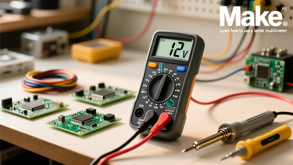

The Anatomy of a Voltage Reading Failure
When a circuit is known to be live but your digital multimeter (DMM) reads 0.00V, or worse, fluctuates wildly, you are facing a diagnostic bottleneck. Understanding how to test volts on a digital multimeter isn't merely about turning a dial; it is about systematically eliminating equipment error, environmental noise, and operator mistakes. Before diving into the matrix of common failures, we must understand the signal path. Voltage travels from the probe tip, through the stranded copper wire, into the banana jack, across an internal shunt or high-impedance resistor network, into the Analog-to-Digital Converter (ADC), and finally to the display.
Failures typically occur at the physical connection points. According to SparkFun's comprehensive multimeter tutorial, the most common point of failure for erratic voltage readings is internal probe wire breakage. The copper strands often snap just behind the stress relief boot near the probe tip due to repeated bending. If your meter reads a stable 120V AC but drops to 0V when you wiggle the probe wire, the issue is mechanical, not electrical.
Step-by-Step Execution: Testing Volts Correctly
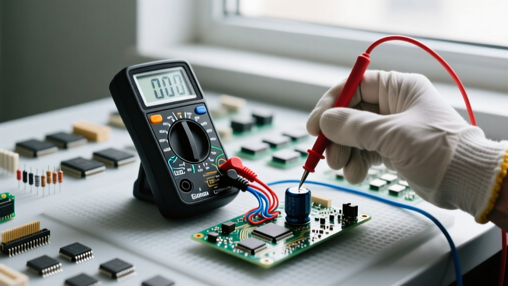
When technicians ask how to test volts on a digital multimeter without getting phantom readings, the answer always comes down to impedance, domain selection, and probe integrity. Follow this rigorous sequence to ensure your baseline is accurate.
1. Visual and Continuity Check of Probes
Before touching a live circuit, set your DMM to the continuity/resistance setting (Ω). Short the red and black probe tips together. A healthy set of silicone test leads should display a resistance between 0.1Ω and 0.4Ω. If the reading exceeds 1.0Ω, or if it fluctuates when you bend the wire, discard the leads immediately. High probe resistance will artificially drag down voltage readings on high-impedance circuits.
2. Selecting the Correct Domain (AC vs. DC)
Ensure the dial is set to the correct voltage type. V~ (or VAC) is for alternating current (mains power, transformers). V⎓ (or VDC) is for direct current (batteries, solar panels, PCB logic rails). Applying a DC setting to an AC circuit will usually result in a reading near zero or a flashing error, while applying an AC setting to a DC battery will yield unpredictable, fluctuating decimals.
3. Range Selection and True-RMS Verification
If you are using a manual-ranging meter, always start at the highest voltage range (e.g., 600V or 1000V) and step down to maximize resolution. Furthermore, if you are measuring non-linear loads like Variable Frequency Drives (VFDs) or LED drivers, a standard averaging meter will read 10% to 20% lower than the actual voltage. You must use a True-RMS meter (like the Fluke 87V or Brymen BM235) to accurately calculate the heating equivalent of distorted sine waves.
Troubleshooting Matrix: Erratic Readings & Solutions
When your readings defy logic, use this diagnostic matrix to isolate the fault. This framework separates operator error from hardware failure and environmental interference.
| Symptom Displayed | Probable Root Cause | Diagnostic Fix & Action |
|---|---|---|
| 'OL' or '1' on the far left | Over-limit condition. The voltage exceeds the current range setting. | Switch to a higher voltage range immediately. If already on 1000V, verify you are not measuring medium-voltage lines by mistake. |
| Fluctuating decimals (e.g., 0.014V to 0.089V) | High-impedance input picking up ambient electromagnetic interference (EMI). | Short the probes together. If it reads 0.000V, the meter is fine; the circuit is floating. Connect a pull-down resistor to the circuit to stabilize. |
| Reads exactly 0V on a known live circuit | Blown internal DMM fuse or broken probe wire. | Test probes on continuity. If probes are good, open the DMM battery compartment to inspect the HRC ceramic fuses. (Note: Voltage testing usually bypasses the fuse, but some meter architectures route through it). |
| Reads 40V-60V on a disconnected wire | 'Ghost Voltage' caused by capacitive coupling from adjacent live wires. | Engage the 'LoZ' (Low Impedance) mode on your meter to bleed off the phantom capacitive charge. |
| Erratic numbers + 'Low Battery' icon | ADC reference voltage is collapsing due to depleted battery. | Replace the 9V or AA batteries. Never trust a voltage reading from a DMM with a low battery indicator; the internal voltage reference is compromised. |
Advanced Diagnostics: Ghost Voltages and High-Impedance Traps
One of the most frustrating scenarios when learning how to test volts on a digital multimeter is encountering 'ghost voltages.' Modern DMMs have an input impedance of roughly 10 Megohms. While this is excellent for preventing the meter from loading down sensitive circuits, it acts as an antenna for capacitive coupling. If a dead, disconnected wire is routed in the same conduit as a live 120V AC wire, the electromagnetic field can induce a phantom voltage of 40V to 80V on the dead wire.
To troubleshoot this, you need a meter equipped with a Low-Impedance (LoZ) mode, such as the Fluke 117. When LoZ is engaged, the meter drops its internal impedance to roughly 3 kilohms. This creates a small load that instantly bleeds off the ghost voltage, dropping the reading to a true 0.00V. If your meter lacks a LoZ button, you can simulate this effect by plugging a specialized low-impedance adapter (like the Fluke TL225) into your test leads, which contains an internal resistor to shunt the phantom energy.
Safety Protocols: CAT Ratings and Arc Flash Mitigation
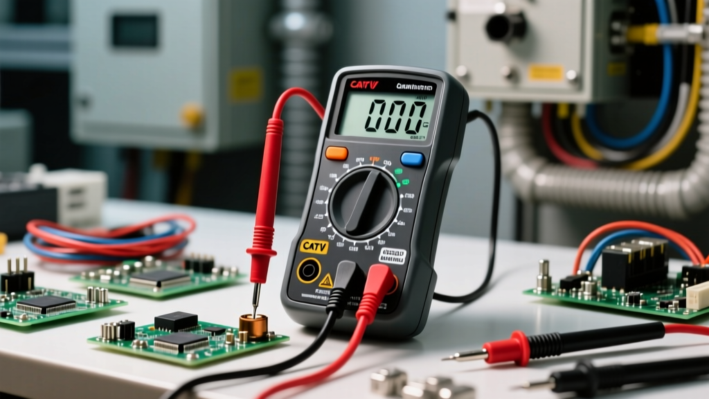
Voltage testing is inherently dangerous. The IEC 61010-1 standard dictates Measurement Categories (CAT) to ensure that a transient voltage spike (like a lightning strike hitting a utility pole miles away) doesn't cause your meter to explode in your hands. As outlined by the Fluke safety guidelines on measurement categories, a CAT III 600V meter is designed to withstand an 8,000V transient impulse, whereas a CAT II 600V meter is only rated for 4,000V.
Critical Safety Warning: Never use a CAT II rated multimeter to test voltage at a main service panel or outdoor utility lines. The transient energy at the origin of installation requires a minimum of CAT III 1000V or CAT IV 600V. Furthermore, always wear arc-rated PPE and safety glasses when probing exposed busbars. Refer to the OSHA Electrical Safety Guidelines for strict compliance regarding approach boundaries and PPE requirements.
Always inspect the probe insulation for micro-tears before testing. A 1000V rated probe with a 2mm nick in the silicone can arc over to your hand if you breach the safe grip boundary. Ensure your fingers are strictly behind the tactile finger guards on the probe handles. By combining rigorous equipment checks, an understanding of impedance traps, and strict adherence to CAT safety ratings, you transform voltage testing from a guessing game into a precise, repeatable science.