
The Anatomy of a Voltage Test: Quick Reference
Whether you are troubleshooting a dead automotive battery, verifying a residential wall outlet, or debugging a custom PCB, understanding how to use a multimeter to test voltage is the most foundational skill in electrical diagnostics. Voltage (electromotive force) is the pressure that pushes electrons through a conductor. Measuring it correctly requires more than just touching probes to wire; it demands an understanding of circuit impedance, safety categories, and waveform distortion.
This cheat sheet bypasses the fluff and provides a field-ready reference for electricians, HVAC technicians, and electronics hobbyists. We will cover exact dial settings, real-world expected readings, and advanced troubleshooting for 'ghost' voltages.
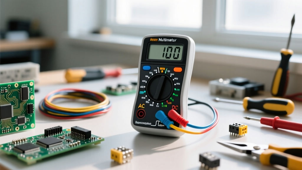
Port Selection & Probe Anatomy
Before turning the dial, you must configure your test leads. Incorrect port selection is the leading cause of blown internal fuses and catastrophic meter failure.
- COM (Common) Port: Always insert the black probe here. This is your reference ground or neutral point.
- V/Ω/mA Port: Always insert the red probe here for voltage testing. This port is protected by the meter's internal high-rupture-capacity (HRC) fuse.
- 10A / High Current Port: Never use this port for voltage testing. Doing so creates a dead short across your voltage source, which will trip the breaker, destroy the meter, or cause an arc flash.
The Core Dial Settings: AC vs. DC
Multimeters separate voltage into two distinct domains. Selecting the wrong domain will result in a reading of zero or erratic, fluctuating numbers.
| Symbol on Dial | Measurement Type | Current Flow | Common Applications |
|---|---|---|---|
| V⎓ (or VDC) | Direct Current Voltage | Unidirectional (Constant polarity) | Batteries, solar panels, PCB logic, USB power, automotive systems. |
| V~ (or VAC) | Alternating Current Voltage | Bidirectional (Sinusoidal wave) | Wall outlets, mains distribution, transformers, HVAC line voltage. |
True-RMS vs. Average-Responding: A Critical Distinction
When testing AC voltage, the type of meter you use dictates your accuracy. Cheap, average-responding multimeters (like the $20 hardware store specials) assume a perfect, clean sine wave. They measure the peak voltage and multiply it by 0.707 to display the RMS (Root Mean Square) value. However, if you are testing a circuit with a dimmer switch, a variable frequency drive (VFD), or LED drivers, the waveform is chopped or distorted. An average meter will give wildly inaccurate readings in these scenarios. You must use a True-RMS multimeter (such as the Fluke 87V or Klein Tools MM700) which samples the actual waveform to calculate the true heating value of the voltage, as detailed in the All About Circuits multimeter guide.
Step-by-Step Protocol: How to Use a Multimeter to Test Voltage
Follow this standardized protocol to ensure accurate readings and maintain personal safety.
- Visual Inspection: Check probe insulation for cracks or exposed wire. Verify the meter's CAT rating matches your environment (see safety section below).
- Probe Connection: Black to COM, Red to V/Ω.
- Domain Selection: Turn the dial to V⎓ for DC or V~ for AC.
- Range Selection (If Manual Ranging): Always start at the highest range (e.g., 600V or 1000V) and step down to increase resolution. If your meter is Auto-Ranging, simply select the V domain and let the microcontroller handle the scaling.
- Probing Technique:
- For Outlets: Use the 'one-hand rule'. Keep one hand in your pocket or behind your back to prevent current from crossing your chest in the event of a shock. Insert the red probe into the hot (shorter) slot, and black into the neutral (longer) slot.
- For PCBs/Terminals: Use probe tips with fine needles. Brace your hands against the chassis to prevent slipping and shorting adjacent SMD components.
- Read and Record: Wait for the reading to stabilize (approx. 1-2 seconds). Engage the 'HOLD' button if working in a dark or cramped enclosure.
Real-World Voltage Cheat Sheet & Expected Readings
Use this table as a quick-reference benchmark when diagnosing common electrical systems. Deviations from these tolerances usually indicate a failing component, excessive voltage drop, or grid issues.
| System / Source | Domain | Nominal Voltage | Acceptable Range / Notes |
|---|---|---|---|
| AA / AAA Alkaline Battery | DC | 1.5V | New: ~1.60V. Dead: <1.20V under load. |
| Automotive 12V Lead-Acid | DC | 12.6V (Resting) | Engine Running (Alternator): 13.7V - 14.7V. >15V indicates a bad voltage regulator. |
| US Residential Receptacle | AC | 120V | ANSI C84.1 Tolerance: 114V to 126V. |
| EU / UK Residential Mains | AC | 230V | Harmonized Tolerance: 216V to 253V. |
| USB-C Power Delivery (PD) | DC | 5V / 9V / 12V / 20V | Requires negotiation. Default un-negotiated state is 5V. |
| 24V HVAC Control Board | AC | 24V | Measured across 'R' and 'C' terminals. Usually reads 26V-28V unloaded. |
Advanced Troubleshooting: Ghost Voltages & LoZ
One of the most confusing phenomena for apprentices learning how to use a multimeter to test voltage is the 'ghost voltage' or 'phantom voltage'. This occurs when unenergized wires run parallel to energized wires in the same conduit. Capacitive coupling induces a small voltage on the dead wire. A high-impedance digital multimeter (DMM) will read this as 40V to 80V, leading technicians to believe a circuit is live when it is not.
Pro Tip: To eliminate ghost voltages, use a meter with a LoZ (Low Impedance) function, such as the Fluke 117. LoZ switches the meter's internal impedance from 10 Megohms down to roughly 3 kilohms, providing a path for the capacitive phantom current to bleed off, dropping the display to a true 0.0V.
If your meter lacks LoZ, you can achieve the same result by using a solenoid voltage tester (a 'Wiggy') or by placing a 10k-ohm resistor in parallel with your probes to act as a bleed load.
Multimeter Safety: CAT Ratings & Internal Fusing
Voltage testing carries inherent risks, particularly when dealing with mains power. The OSHA Electrical Safety Guidelines mandate the use of properly rated test equipment. You must match your meter's Category (CAT) rating to the environment:
- CAT II: Single-phase receptacle connected loads (appliances, portable tools).
- CAT III: Three-phase distribution, including single-phase commercial lighting and fixed motor loads. (This is the standard for most industrial and commercial electricians).
- CAT IV: Three-phase at utility connection, outdoor service entrance, and meter bases. (Required for linemen and heavy industrial troubleshooting).
For a deeper dive into why these categories matter, review the Fluke CAT Ratings Explained guide. Remember that a CAT III 1000V rating is vastly superior to a CAT II 1000V rating due to the transient overvoltage (impulse) testing requirements. Furthermore, always verify that your meter uses sand-filled ceramic HRC fuses rather than cheap glass fuses. Glass fuses can shatter and vaporize copper inside the meter during a high-energy arc fault, turning the multimeter into a fragmentation grenade in your hands.
Final Verification Step
Before and after every critical voltage test, use the Live-Dead-Live method. Test a known live source (like a verified outlet) to ensure the meter is functioning, test your target circuit, and then test the known live source again. This guarantees your meter's fuse didn't blow silently during the test, leaving you with a false 'dead' reading on a lethal circuit.