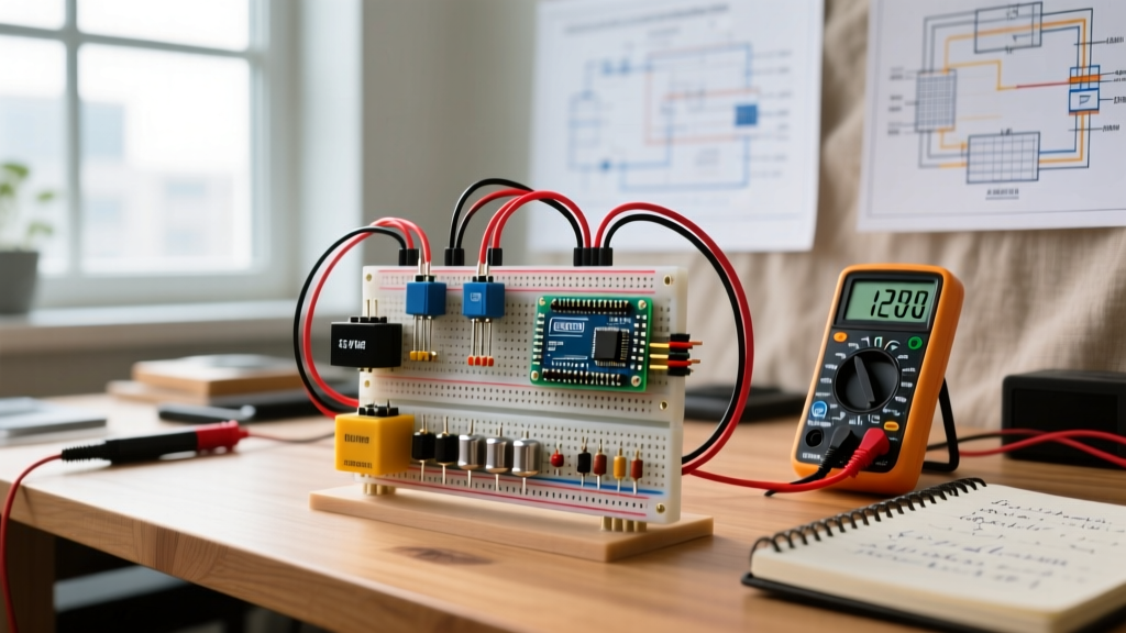
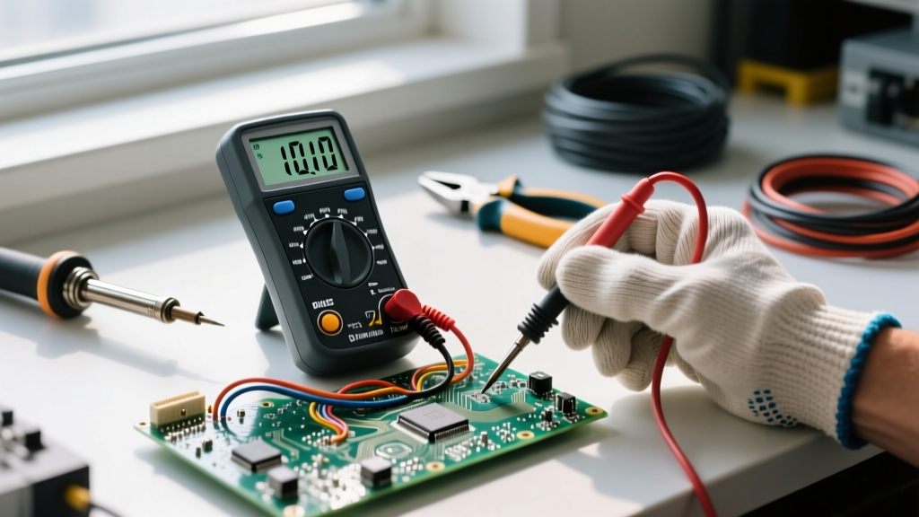
Multimeter checking is the systematic process of verifying circuit integrity by comparing measured electrical values against known nominal ranges. For a standard US 120V residential receptacle, a good reading is 114V–126V AC. For a 12V LiFePO4 battery, a healthy resting state reads 13.2V–13.6V DC. Relying on abstract 'power present' indicators is insufficient for modern diagnostics; precise numerical verification is required to identify voltage drop, open neutrals, and degraded connections before they cause thermal failures.
Meter Setup and Safety Category (CAT) Requirements
Before taking a single measurement, you must match your meter's safety rating to the environment. The IEC 61010-1 standard defines measurement categories based on transient overvoltage risks, not just steady-state voltage. A 1000V CAT II meter is not equivalent to a 600V CAT III meter. The CAT III rating accounts for the high-energy transients that can occur on branch circuits when large inductive loads (like HVAC compressors) switch off.
Any procedure involving physical contact with mains wiring (>50V AC) requires strict safety protocols. Always de-energize the circuit at the breaker panel, apply a lockout/tagout device, and verify the circuit is dead with a tested meter before removing any cover plates or touching bare terminals. Local electrical codes (NEC-style guidance) may require a licensed electrician for panel work.
Standard Meter Setup Block
- Dial Position: Select V~ (AC Volts) for mains and household wiring, or V⎓ (DC Volts) for batteries, solar arrays, and electronics. Never leave the dial on Ohms (Ω) or Continuity when moving to a new job site.
- Lead Jacks: Black lead always goes in COM (Common). Red lead goes in V/Ω/Hz for voltage and resistance. Never leave the red lead in the 10A or mA current jacks when measuring voltage; this creates a dead short.
- Range Selection: Use Auto-Range for general troubleshooting. Switch to Manual Range (e.g., locking to the 200V scale) if the meter's auto-ranging algorithm is 'hunting' and failing to settle on fluctuating signals.
Expected Readings and Probe Placement Reference
The most common point of failure in diagnostic work is not knowing what a 'good' number actually looks like. Nominal voltage is rarely the exact number printed on the label. According to ANSI C84.1, US utility delivery allows for a ±5% variance on a 120V system, meaning your meter should read between 114V and 126V under normal load conditions. The table below provides the exact numerical benchmarks for common test points.
| Test Point | Dial Setting | Probe Placement | Expected Good Reading | Bad Reading / Fault Indication |
|---|---|---|---|---|
| 120V Receptacle (Hot-Neutral) | V~ (AC Volts) | Red to shorter slot (Hot), Black to longer slot (Neutral) | 114.0V – 126.0V | < 110V (severe voltage drop/loose neutral) or 0V (open circuit/tripped breaker) |
| 120V Receptacle (Hot-Ground) | V~ (AC Volts) | Red to shorter slot (Hot), Black to round U-ground | 114.0V – 126.0V | 0V (open ground fault) or ~60V (bootleg ground or neutral-to-ground bond fault) |
| 12V LiFePO4 Battery Pack | V⎓ (DC Volts) | Red to POS terminal, Black to NEG terminal | 13.2V – 13.6V (resting) | < 12.0V (deeply depleted) or > 14.6V (overcharge state / BMS failure) |
| 5V DC USB VBUS (Type-A) | V⎓ (DC Volts) | Red to outer VBUS pin, Black to metal shell/ground | 4.75V – 5.25V | < 4.5V (excessive cable voltage drop) or 0V (blown polyfuse on host board) |
| Automotive Mini Blade Fuse | Ω (Ohms) / Continuity | Across both exposed top test blades (circuit de-energized) | < 1.0 Ω (or audible beep) | OL / Infinite resistance (blown internal element) |
When checking the 120V Hot-Ground path, a reading that perfectly matches the Hot-Neutral reading confirms a solid equipment grounding conductor (EGC) back to the main panel. If the Hot-Ground reading is significantly lower than Hot-Neutral, you likely have a high-resistance connection on the neutral bus or a shared neutral carrying unbalanced return current from a multi-wire branch circuit (MWBC).
Mistakes That Yield Misleading Readings
Modern digital multimeters (DMMs) like the Fluke 117 or Brymen BM235 feature high input impedance, typically 10 MΩ. While this prevents the meter from loading down sensitive circuits, it makes the meter highly susceptible to picking up stray electromagnetic fields, leading to false diagnostics.
1. Ghost Voltage (Capacitive Coupling)
If you probe a disconnected wire running in the same conduit as a live 120V wire, your meter might display 40V to 80V AC. This is 'ghost voltage' induced by capacitive coupling. It has virtually zero current capacity. If you attempt to wire a load based on this reading, it will collapse to 0V immediately. The Fix: Use your meter's LoZ (Low Impedance) mode if equipped, which inserts a lower resistance path to bleed off phantom voltages, or verify with a solenoid-style wiggy tester.
2. Measuring Resistance on a Live Circuit
Switching the dial to Ohms (Ω) or Continuity while the circuit is energized forces the meter to inject its own test current into an active voltage source. At best, this blows the internal 0.5A HRC fuse. At worst, it arcs across the internal PCB traces, permanently destroying the meter and risking injury. Always verify the circuit is de-energized with the V~ setting before switching to Ω.
3. The 10A Current Jack Trap
The most catastrophic bench mistake is leaving the red probe in the 10A (or mA) current jack, turning the dial to Volts, and probing a mains outlet. The current jack is essentially a shunt resistor (a near dead-short). Placing this across 120V AC creates an immediate phase-to-neutral short circuit, resulting in a massive arc flash. Always physically move the red lead back to the V/Ω jack the second you finish a current measurement.
Step-by-Step Verification for a Dead 120V Branch Circuit
Before replacing a damaged receptacle or hardwiring a new appliance, you must verify the branch circuit is truly dead. Relying solely on a breaker label is a leading cause of jobsite shocks, as panels are frequently mislabeled or circuits are tandem-fed.
- De-energize and Lockout: Turn off the target breaker at the main service panel. Apply a physical breaker lockout device to prevent accidental re-engagement.
- Verify the Meter on a Known Live Source: Before trusting your meter on the dead circuit, test it on a known live receptacle (or use a dedicated proving unit). Confirm the meter reads ~120V AC. This proves your leads and internal fuses are intact.
- Test the Target Circuit (Phase 1): Insert probes into the target receptacle (Hot to Neutral, then Hot to Ground). The meter must read 0.00V or < 0.5V (stray millivolts). If it reads line voltage, you have the wrong breaker.
- Test the Target Circuit (Phase 2): Switch the meter to AC Volts and test Neutral to Ground. This should also read 0.00V. A reading of 2V–5V here indicates a shared neutral that is still active on a different breaker.
- Re-verify Meter: Test your meter on the known live source one final time to ensure the meter did not fail or blow a fuse during the dead-circuit testing.
- Proceed with Physical Work: Only after passing all verification steps should you remove the receptacle yoke screws and expose the bare terminal wiring.
Accurate multimeter checking is less about the tool itself and more about the diagnostic framework you apply to the numbers. By anchoring your expectations to ANSI and IEC standards rather than nominal labels, and by actively filtering out high-impedance ghost voltages, you transition from simply 'checking for power' to genuinely mapping circuit health. For further reading on measurement safety standards, consult the OSHA electrical safety guidelines and the NFPA 70 (National Electrical Code) documentation.