
The Anatomy of a DHT11 Failure
The DHT11 temperature and humidity sensor is arguably the most ubiquitous environmental component in the DIY electronics space. Priced at under two dollars, it is the default choice for beginners learning microcontrollers. However, its low cost is matched only by its notoriously finicky communication protocol. Unlike standard I2C or SPI sensors, the DHT11 uses a proprietary single-wire serial protocol that relies on precise microsecond timing. When this timing is disrupted by interrupt latency, voltage drops, or parasitic capacitance, the sensor fails silently or returns garbage data.
If you are staring at a serial monitor full of NaN (Not a Number) readings, Checksum Failed errors, or complete timeouts, you are not alone. This guide bypasses generic advice and dives deep into the electrical and programmatic failure modes of the DHT11, providing actionable frameworks to restore stability to your environmental monitoring projects.
Diagnostic Matrix: Symptom to Solution
Before rewriting your code or swapping out components, map your specific serial output to the hardware or software fault causing it. Use this diagnostic matrix to isolate the root cause.
| Symptom / Serial Output | Probable Root Cause | Immediate Hardware / Code Fix |
|---|---|---|
NaN for both Temp & Humidity |
Missing pull-up resistor or data wire disconnected. | Verify 4.7kΩ pull-up on data line; check continuity. |
Checksum Failed |
Interrupt latency shifting bit-read timings (common on ESP32/ESP8266 with WiFi active). | Disable interrupts during read, or upgrade to DHT22/AHT20. |
Timeout waiting for start signal |
Sensor is powered down, or logic level mismatch (3.3V MCU to 5V sensor). | Measure VCC at sensor pins; add logic level shifter. |
| Readings stuck at exactly 0.0 | Sampling rate too high (exceeding 1Hz limit). | Increase delay between reads to minimum 1000ms (preferably 2000ms). |
Step 1: The Pull-Up Resistor Dilemma
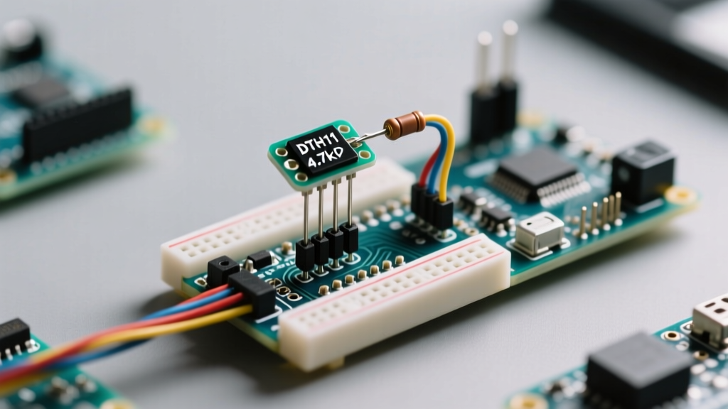
The most frequent cause of DHT11 failure in bare-component circuits is the omission of a pull-up resistor. The DHT11 data line is open-drain. It can pull the line LOW to transmit data, but it cannot drive it HIGH. The microcontroller's internal pull-up resistors (typically 20kΩ to 50kΩ) are far too weak to pull the line high fast enough for the DHT11's high-speed timing requirements.
Calculating the Correct Pull-Up Value
- 5V Logic (Arduino Uno/Mega): Use a 4.7kΩ resistor between the VCC (5V) and the Data pin. This provides enough current to charge the parasitic capacitance of the wire quickly, ensuring sharp rising edges.
- 3.3V Logic (ESP32/ESP8266/Raspberry Pi Pico): Use a 10kΩ resistor between 3.3V and the Data pin. A 4.7kΩ resistor on a 3.3V rail may draw excessive current and cause voltage sag, while a 10kΩ resistor provides the optimal RC time constant for 3.3V logic thresholds.
Pro-Tip: If you are using a 3-pin DHT11 module (mounted on a small PCB), the 10kΩ pull-up resistor is already soldered onboard. Do not add an external pull-up resistor when using the module, as paralleling resistors will lower the total resistance and potentially cause logic HIGH voltage drops.
Step 2: Logic Level and Voltage Drops
The DHT11 operates on a supply voltage range of 3.3V to 5.5V. However, the output voltage on the data pin will match the supply voltage. This creates a critical hazard when interfacing with modern 3.3V microcontrollers.
If you power a bare DHT11 with 5V to ensure stability, its data pin will output 5V HIGH signals. Feeding a 5V signal directly into an ESP32 or Raspberry Pi GPIO pin will eventually degrade or destroy the silicon due to overvoltage. Conversely, if you power the DHT11 with 3.3V, the output HIGH signal is 3.3V, which is safe for the ESP32 but might fall below the reliable logic HIGH threshold (typically 0.7 x VCC) if the microcontroller is operating on a noisy 5V rail.
The Fix: Always match the DHT11 VCC to the microcontroller's logic level. For 3.3V boards, power the DHT11 from the 3.3V pin and use a 10kΩ pull-up to 3.3V. For further isolation and noise immunity, consult comprehensive wiring diagrams like those provided in the Random Nerd Tutorials ESP32 DHT Guide, which detail safe 3.3V implementations.
Decoding NaN and Checksum Errors in Code
When using the standard Adafruit DHT Sensor Library, the read() function operates by disabling global interrupts, sending a start pulse, and bit-banging the data line. The DHT11 transmits 40 bits of data (16 bits humidity, 16 bits temperature, 8 bits checksum). If the microcontroller's interrupt latency causes it to miss a microsecond pulse, the bits shift, and the checksum fails.
The ESP32 WiFi Interrupt Conflict
The ESP32 is a dual-core powerhouse, but its WiFi and Bluetooth stacks generate thousands of background interrupts per second. When the DHT library disables interrupts to read the sensor, the WiFi stack buffers data. If the read takes too long, or if the RTOS preempts the core, the timing is ruined, resulting in a Checksum Failed error.
Software Mitigation Strategies:
- Increase Retry Limits: Wrap your read function in a retry loop. It is normal for the DHT11 to fail 1 in 10 reads on an ESP32. Discard NaNs and keep the last known good value.
- Core Pinning: Pin your sensor reading task to Core 0, leaving Core 1 exclusively for the WiFi stack and Arduino loop.
- Non-Blocking Libraries: Consider switching to libraries like
DHT_sensor_library_non_blockingwhich use hardware timers instead of delay-based bit-banging, though hardware timer support varies by board.
Hardware Limitations: Wire Length and Capacitance
The DHT11 protocol was designed for short-distance, on-PCB communication. The single-wire bus acts as a capacitor. As you increase the wire length, the parasitic capacitance increases, rounding off the sharp digital edges required for microsecond timing.
- Under 1 Meter: Standard 22 AWG jumper wires work perfectly with a 4.7kΩ pull-up.
- 1 to 5 Meters: You must lower the pull-up resistor value (e.g., to 2.2kΩ or 1kΩ) to provide more current to charge the wire capacitance. Use shielded twisted-pair cable (like Cat5e), tying the shield to GND at the microcontroller end only to prevent ground loops.
- Over 5 Meters: The DHT11 will fail reliably. The protocol simply cannot overcome the RC delay of long wires. You must switch to an I2C sensor or use a localized microcontroller to transmit the data via RS485 or WiFi.
Sensor Comparison: When to Abandon the DHT11
Troubleshooting a DHT11 often leads to the realization that the component itself is the bottleneck. If your project requires high precision, fast sampling, or long-term stability, it is time to upgrade. Below is a comparison of common environmental sensors to help you pivot your design.
| Sensor Model | Protocol | Temp Accuracy | Humidity Accuracy | Max Sample Rate | Best Use Case |
|---|---|---|---|---|---|
| DHT11 | Proprietary 1-Wire | ±2.0°C | ±5% RH | 1 Hz | Basic classroom demos, simple fan triggers. |
| DHT22 (AM2302) | Proprietary 1-Wire | ±0.5°C | ±2% RH | 0.5 Hz | Greenhouses, weather stations (short wires). |
| AHT20 / AHT21 | Standard I2C | ±0.3°C | ±2% RH | Fast (I2C limited) | Modern smart home nodes, ESP32/ESP8266 projects. |
| BME280 | I2C / SPI | ±1.0°C | ±3% RH | Fast (I2C/SPI) | Altitude/Pressure tracking, professional IoT nodes. |
As noted in the Adafruit DHT Learning Guide, while the DHT11 is a great learning tool, the I2C-based AHT20 or BME280 eliminate 99% of the timing and checksum headaches inherent to the proprietary 1-Wire protocol.
Advanced Oscilloscope Diagnostics
If you have verified wiring, pull-ups, and code, but the sensor still fails, it is time to put an oscilloscope on the data line. A healthy DHT11 communication sequence looks like this:
- MCU Start Signal: The microcontroller pulls the line LOW for at least 18 milliseconds, then releases it HIGH for 20-40 microseconds.
- Sensor Response: The DHT11 pulls the line LOW for 80 microseconds, then HIGH for 80 microseconds.
- Data Bits: Each bit starts with a 50µs LOW pulse. A logic '0' is followed by a 26-28µs HIGH pulse. A logic '1' is followed by a 70µs HIGH pulse.
If the 80µs response pulse is missing, the sensor is dead or unpowered. If the data bits show rounded, sloping edges instead of sharp square waves, your pull-up resistor is too weak for the wire capacitance. If the HIGH pulses for logic '1' are consistently shorter than 70µs, the sensor's internal oscillator is drifting due to extreme temperature or manufacturing defects.
Final Verdict and Pro-Tips
The DHT11 sensor is a rite of passage for electronics hobbyists. Troubleshooting it teaches invaluable lessons about open-drain outputs, pull-up resistors, logic level shifting, and the fragility of software-based bit-banging protocols. Always remember the golden rules: respect the 1Hz sampling limit, use the correct pull-up resistor for your logic voltage, and implement software retry loops to handle inevitable checksum failures. When reliability becomes paramount, let the diagnostic data guide you toward an I2C-based upgrade like the AHT20 or BME280, leaving the timing headaches behind.